
User Manual


> > > > > > > > > > > > > > > > > > > > > > > > > > > > > > > > > > > > > > > > > > > > > > > > > > > > > > > > > > > > > > > > > > > >
88
\
B E D I E N E L E M E N T E
B E D I E N E L E M E N T E
B E D I E N E L E M E N T E
> > > > > > > > > > > > > > > > > > > > > > > > > > > > > > > > > > > > > > > > > > > > > > > > > > > > > > > > > > > > > > > > > > > >
Manual SDs-01 D 3.2.2003 17:45 Uhr Seite 3
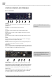
CONTROL ELEMENTS AND TERMINALS
MC-1.1+ Front Panel
1 POWER
This red LED lights up when the unit is switched on with the rear panel
POWER switch.
2 SELECT
Use this key to access the different functional menus.
3 DATA
Use this key to select a function from a specific functional menu.
4 MODE
This function menu allows to select all digital audio format conversion
modes available.
5 AUDIO IN
This function menu allows to select the digital audio formats for conver-
sion.
6 SCMS
This function menu offers three different ways to encode the outgoing
S/P-DIF optical and coaxial digital audio signals.
7 STATUS
This menu indicates various signal statuses of incoming S/P-DIF optical or
coaxial digial audio signals by means of status LEDs.
8 AES3id OUT
These two outputs transmit two AES3id digital audio stereo or blank frame
signals in compliance with the AES3id–2001 or AES 11–1997/2003 standards.
The output impedance is 75 Ω (BNC connectors, female).
MC-1.1+ Rear Panel
1 S/P-DIF OUT
These four S/P-DIF outputs, available as 2 x optical (»OP«) and 2 x coaxial
(»CO«) interfaces, transmit an optical S/P-DIF and an unbalanced electrical
S/P-DIF digital audio or blank frame signal in compliance with the IEC 60958
standard. The coaxial interface impedance is 75 Ω. (cinch connector), the
optical interface offers a Toshiba Toslink
TM
connector, EIAJ standard.
2 AES3/11 OUT
These two outputs transmit a balanced digital AES3 audio or AES11 blank
frame signal compliant with AES 3–1992 (R1997) and AES 11–1997/2003.
The output impedance is 110 Ω (XLR connectors, male).
9
MC-1.1 Rear Panel
MC-1.1+ Front Panel
Refer to the OPERATIONS chapter for more
information.
For detailed specifications on all terminals,
refer to the »Pin Assignment of the
Connectors« and »Technical Data« in the
chapter APPENDIX.
4
3
2
1
1
2
3
4
5
6
5
6
7
8