
Technical data


> > > > > > > > > > > > > > > > > > > > > > > > > > > > > > > > > > > > > > > > > > > > > > > > > > > > > > > > > > > > > > > > > > > >
88
\
B E D I E N E L E M E N T E
B E D I E N E L E M E N T E
B E D I E N E L E M E N T E
> > > > > > > > > > > > > > > > > > > > > > > > > > > > > > > > > > > > > > > > > > > > > > > > > > > > > > > > > > > > > > > > > > > >
Manual SDs-01 D 3.2.2003 17:45 Uhr Seite 3
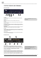
CONTROL ELEMENTS AND TERMINALS
MC-4 Front Panel
1 POWER
This red LED lights up when the unit is switched on with the rear panel
POWER switch.
2 MENU
The push-button selects one of the available function menus.
3 SELECT
Use this push-button to select a function within a specific function menu.
4 MODE + AUDIO IN
This function menu allows to adjust all available conversion modes (LED
line »MODE«) in combination with the corresponding digital audio formats
(LED line »AUDIO IN«) .
5 REFERENCE
This function menu allows to select the master clock reference for synchro-
nization of the format conversion sections as well as the SRCs.
6 STATUS
This menu indicates various signal statuses of the incoming master clock
reference signal and the digital audio signal as well as the SMUX coding of
the ADAT
TM
output signal.
7 REF CLOCK IN
This menu indicates the clock rates of the incoming digital audio signal or
of the master clock reference signal.
MC-4 Rear Panel
1 AES11 REF IN
This input receives a balanced digital AES11 blank frame signal in com-
pliance with AES11–1997/2003 as master clock reference for the SRCs.
Alternatively, an AES3 digital audio signal in compliance with AES3 –1992
(R1997) or a S/PDIF digital audio signal aligned to IEC60958 can be input as
well. The input impedance is 110 Ω (XLR connector, female).
2 AES3 IN + OUT CHAN 1– 8
This interface receives and transmits 8 channels of AES3 digital audio sig-
nals each in compliance with AES3 –1992 (R1997). Alternatively, the 8 inputs
can also be feeded with S/PDIF digital audio signals aligned to IEC60958.
The input and output impedances are 110 Ω. The pin assignment of the
25pin D-Sub connector complies with Yamaha, AKAI, Mackie and others, too.
9
Refer to the OPERATIONS chapter for more
information.
For detailed specifications on all terminals,
refer to the »Pin Assignment of the
Connectors« and »Technical Data« in the
chapter »APPENDIX«.
4
3
2
1
1
2
4
6
7
5
6
7
3
5
4