
Manual


\\\\\\\\\\\\\
CONTROL ELEMENTS
CONTROL ELEMENTS
CONTROL ELEMENTS
>>>>>>>>>>>>>>>>>>>>>>>>>>>>>>>>>>>>>>>>>>>>>>>>>>>>>>>>>>>>>>>>>>>>
>>>>>>>>>>>>>>>>>>>>>>>>>>>>>>>>>>>>>>>>>>>>>>>>>>>>>>>>>>>>>>>>>>>>
88
Manual SDs-01 E 3.2.2003 18:26 Uhr Seite 6
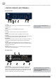
2 WCLK IN
+
OUT
The above BNC connector (IN) receives a Word Clock or so-called »Super
Clock« signal as master clock reference for the SRCs. The below BNC con-
nector (OUT) transmits a low-jitter Word Clock signal based on the internal
clock base or the selected external clock reference signal. If format con-
versions only are carried out, the WCLK output sends a Word Clock signal
extracted from the selected digital audio reference signal.
The impedances of both connectors are 75 Ω (BNC connectors, female).
3 ADAT
TM
IN
These two optical inputs receive digital audio multichannel signals incom-
pliance with the Alesis ADAT
TM
format. Input »A« alone accepts ADAT
TM
signals up to 50.0kHz. For receiving ADAT
TM
signals with higher clock rates
up to 192.0kHz, both inputs »A« and »B« are used simultaneously (Toslink
TM
connector, EIAJ standard).
4 AES3 IN + OUT CHAN 1– 8
This interface receives and transmits 8 channels of AES3 digital audio sig-
nals each in compliance with AES3 –1992 (R1997). Alternatively, the 8 inputs
can also be feeded with S/P-DIF digital audio signals aligned to IEC60958.
The input and output impedances are 110 Ω. The pin assignment of the
25pin D-Sub connector complies with Yamaha, AKAI, Mackie and others, too.
5 ADAT
TM
OUT
These two optical outputs transmit digital audio multichannel signals in
compliance with the Alesis ADAT
TM
format. Eight channel ADAT
TM
with up
to 50.0kHz clock rate are sent to both optical outputs, enabling a signal
doubling. For transfering ADAT
TM
signals with higher clock rates up to
192.0kHz, both outputs »A« and »B« are used to split the ADAT
TM
signal, as
described on page 16, under »SMUX2 + SMUX4« (Toslink
TM
connector, EIAJ
standard).
6 S/P-DIF IN/OUT
These interfaces function as receiver and transmitter for S/P-DIF digital
audio signals in compliance with the IEC 60958 standard. Their func-
tion depends on the selected operation mode, which is displayed on the
front panel. The impedances of all connectors are 75 Ω (Cinch connectors,
female).
7 MAINS IN, Power Switch + Power Inlet
This is the main switch for switching the device on and off. Be sure to
make all connections (especially the supplied power cable) properly before
turning on the switch. Heed the SAFETY INSTRUCTIONS at the beginning of
this manual.
Connect the supplied power cable here. Make sure that the power switch
is turned off before connecting the power cable to this inlet and to the
power outlet. Line voltages within the range of 90…260V with a frequen-
cies between 47...440Hz can be applied. The internal power supply will
automatically make all necessary adjustments.
10