
Technical data


������������
� � � � � � � � � � � � � � � � � � � � � � � � � � � � � � � � � � � � � � � � � � � � � � � � � � � � � � � � � � � � � � � � � � � �
� � � � � � � � � � � � � � � � � � � � � � � � � � � � � � � � � � � � � � � � � � � � � � � � � � � � � � � � � � � � � � � � � � � �
��
INSTALLATION
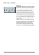
Setting up
The device should be placed as close as possible to the devices to which it
will be connected in order to reduce the amount of cable needed. To avoid
damaging the device chassis and the set-up area, stick the enclosed rubber
feet (4x) evenly to the underside of the device. When installing the unit in a
rack, the rubber feet should not be used for reasons of space!
For installation in 19 racks a corresponding rack-mount kit, MW-01/19,
is an optional extra (order no. 8020-005). In this case ensure that the unit
is placed in the rack in such a way that one height unit is kept free, or
equipped with panels, both above and below the chassis body to allow for
proper air circulation!
Wiring the digital audio inputs
Before using the unit, the interfaces of all units used in the set-up must
be appropriately stacked and connected according to the right format.
The four coaxial S/PDIF inputs should be connected with electric,
unbalanced cables using cinch connectors. According to specifications,
the specific resistance of the cable must be 75Ω.
The optical S/PDIF input should be connected using optical cables in
compliance with Toshibas TOSLINK
TM
standard. The cables used may be
made of plastic or glass fiber. In the case of plastic fiber, do not use any
more than ten meters for reasons of transmission safety. Glass fibers, on
the other hand, can easily transfer data across much greater distances.
The AES/EBU interface should be connected with electric, balanced cables
using XLR connectors. According to specifications, the specific resistance
of the cable must be 110 Ω.
Wiring the Word Clock interfaces
Electric, unbalanced cables with BNC connectors are used to transmit
Word Clock signals. Typically, the corresponding cable qualities are
labeled »RG-59U or RG-59B/U«.
Do not use cables labeled »RG-58U«!
The SMART MERGE Word Clock input is internally terminated with 75Ω,
according to specifications. This termination must be disabled if the
connected Word Clock cable is to be daisy-chained to other devices as
only the last device in a chain may be terminated. Proceed as described in
the appendix under »Disabling the termination«.
If the SMART MERGE Word Clock output is used to synchronize other
devices, ensure that the Word Clock inputs of the connected devices are
properly terminated, except in the case of a daisy chain. On most devices,
the termination of the Word Clock inputs may be activated or interrupted
using a so-called »termination switch«. This switch can be found on the
outside or inside of the device in question.
In the case of devices that do not feature a termination of the Word
Clock input, e.g. RME Hammerfall with Word Clock i/o or Alesis BRC, it is
possible to terminate the connection with an additional BNC-T connector.
Using its middle connector, plug the T connector into the input of the
receiving device. The cable carrying the clock signal is then connected to
one of the side connectors and a 75Ω resistance is connected to the other
side of the BNC-T connector, acting as a BNC terminal connector.
Do NOT expose the unit and its accessories
to rain, moisture, direct sunlight or excessive
heat produced by such heat sources as radia-
tors or spotlights!
Keep cable lengths as short as possible to
minimize loss and possible interference from
other devices!
Optical cables, specially tested for the
transmission of S/PDIF and ADAT
TM
signals,
are available in various lengths from your
MUTEC dealer!
It is imperative to ensure that the output
resistance of the Word Clock cable used is
75 Ω, according to specifications! Using cables
with a different specific resistance can lead to
a drastic deterioration of the signal quality!
This would also jeopardize the perfect syn-
chronization of the devices connected to it.
You should generally avoid »daisy chaining«
Word Clock lines using passive BNC T
connectors for reasons of signal quality or
resulting loss of levels. Should such routing
prove to be unavoidable, no more than three
devices should be routed or connected to one
Word Clock output.
8