
Technical data


������������
� � � � � � � � � � � � � � � � � � � � � � � � � � � � � � � � � � � � � � � � � � � � � � � � � � � � � � � � � � � � � � � � � � � �
� � � � � � � � � � � � � � � � � � � � � � � � � � � � � � � � � � � � � � � � � � � � � � � � � � � � � � � � � � � � � � � � � � � �
��
OPERATION
Thanks to its clear structure and fully automatic functioning, operating
the SMART MERGE is incredibly easy.
Connecting the devices
When selecting which of the SMART MERGE digital audio inputs to use to
connect the devices please note that there are two interfaces available for
each of inputs 1 + 2. Input 1 enables the connection of a S/PDIF or AES/EBU
signal source whereby switching between the two connections is automatic.
The priority here is the AES/EBU input. The presence of a valid AES/EBU
signal precludes reception of any other signal at the S/PDIF input. If the
AES/EBU input is not connected, the S/PDIF input is automatically enabled.
Input 2 enables the connection of a coaxial or an optical S/PDIF signal
source. The optical S/PDIF input has priority here and switching between
interfaces also occurs automatically, as previously described.
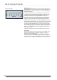
If the inputs receive usable digital audio signals, this is indicated via the
LEDs labeled INPUT 1+4 on the front panel (see figure opposite). If the
LED corresponding to the input is not constantly illuminated, a faulty
incoming signal may be the cause. This could then lead to disruption of
the AES/EBU master signal!
Synchronization
The SMART MERGE does not have its own clock reference. The device must
thus be externally synchronized. This can be done by supplying a Word
Clock or Word Clock x 256 signal (known as Super Clock for ProTools
TM
systems). If there is no available Word Clock signal, the first digital audio
input automatically serves as clock reference for the SMART MERGE. The
device cannot function if there is no Word Clock signal supplied and, at
the same time, the first digital audio input is not connected with a usable
signal!
Should a clock signal be present at the Word Clock input and at the same
time a usable audio signal present at the first digital audio input, the Word
Clock signal always has first priority! Accordingly, the AES/EBU master signal
is output synchronously to the incoming Word Clock signal.
A usable Word Clock signal at the Word Clock input is indicated by the blue
LED LOCK WCLK on the front panel (see figure opposite). If no Word Clock
signal is connected and the first audio input is therefore serving as the clock
reference, the blue LED LOCK INPUT 1 will light up on the front panel.
If the LOCK LED connected to the clock source does not stay lit, continuous
transmission at the AES/EBU master output is not possible!
As the SMART MERGE is completely equipped on the input side with
sampling rate converters, incoming digital audio signals may be
asynchronous. The AES/EBU master signal is thus output synchronously to
the respective reference clock signal - regardless of the clock rate of the
incoming signal!
Thus, in addition to its actual function as a digital mixer, SMART MERGE
enables the integration of non-synchronizable devices in a clock
synchronous studio environment, functioning both as a multi-channel
sampling rate converter and a format converter.
The first mix
Before listening to the first mix signal, the SINGLE / MASTER switch (see
figure opposite) should be set to MASTER in order to make the complete
mix signal available at the AES/EBU master output.
If the signal sources to be mixed as well as a reference clock signal
necessary for synchronization are connected and if the front LEDs indicate
the usability of all signals, SMART MERGE begins the mixing process
automatically no further settings are necessary!
When connecting the SMART MERGE always
ensure that the first digital audio input is
given priority! When no Word Clock signal
is available, the signal present on the first
digital audio input serves as clock reference
for the device.
Signal Inputs
Input- + Lock-Status-LEDs
9
Signal inputs
with priority