
Specifications


Falcon II Outdoor series printers – Maintenance Manual
241
AP-74065, Rev. 1.0, 21/11/03
Step 2 : Select "Adj:HeadSlant".
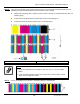
Step 3 : Print "F and B" pattern.
Notes :
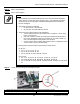
¾ Before adjusting the head forward/backward, move the head fore/aft adjustment
screw until item 3 in following figure reaches 0.5mm. If the adjustment has been
made when the screw is too tight, forward/backward adjustment of heads may
become misaligned.
¾ The reference head is the following.
50, 64 inch spec: The first head.
87 inch spec: The third head from the left.
¾ The three types of printing patterns are listed below:
1st Line: Pattern used in order to adjust row A of heads 2, 3, and 4 using
head 1 as a reference.
2nd Line: In order to confirm the results of the adjustments performed on
the 1st line, this pattern checks to see whether or not row B of heads 3, 2,
and 1 has been adjusted using head 4 as a reference.
3rd Line: Pattern which confirms that identical colour is configured at center
of each nozzle in 4-colour double setting.
¾ Printing pattern is printed with the head sequence shown below:
50: 64 inch
¾ Line 1: 1A, 2A, 1A, 3A, 1A, 4A
¾ Line 2: 1B, 2B, 1B, 3B, 1B, 4B
¾ Line 3: 1A & 4B, 2A & 3B, 3A & 2B, 4A & 1B
87 inch spec
¾ Line 1: 3A, 1A, 3A, 2A, 3A, 4A, 3A, 5A, 3A, 6A, 3A, 7A, 3A, 8A
¾ Line 2: 6B, 8B, 6B, 7B, 6B, 5B, 6B, 4B, 6B, 3B, 6B, 2B, 6B, 1B
¾ Line 3: 1A & 8B, 2A & 7B, 3A & 6B, 4A & 5B, 5A & 4B, 6A & 3B, 7A & 2B, 8A &
1B
Step 4 : Loosen the screw fixing the head stationary plate.
1 = Screw (M2.5x5) fixing the head stationary plate 2 = Fore/Aft Adjustment Screws
3 = 0.5 mm (0.02 in.)