
Specifications


Falcon II Outdoor series printers – Maintenance Manual
67
AP-74065, Rev. 1.0, 21/11/03
4.4. REPLACING BOARD BASES
This chapter explains the procedures for replacing the power source board assembly, mainboard assembly, PCI_Linux
board assembly and cooling fan assembly.
Caution :
When handling circuit boards, do not touch the elements on the board with your bare
hands. Doing so may cause static electricity and break the elements.
4.4.1 Replacing the Mainboard assembly, HDD_Extension board assembly,
HEAD_DRV
board assembly, PCI_Linux board assembly and cooling fan
assembly
Notes :
¾ To replace the board and connect or disconnect the FFC type cable, you should
leave the plug disconnected from the power socket for a while. Otherwise, over-
current could be generated and damage board.
¾ When changing the main substrate assembly, follow "Parameter backup" to backup
the parameter. Failure to do so could cause the life span counters for the waste
fluid tank and tube not to reset, resulting in an overflow of ink inside the printer.
See "Adjustment" for details of other adjustment.
¾ Remove the following parts before replacing the Mainboard assembly,
HDD_Extension board assembly, HEAD_DRV board assembly, PCI_Linux board
assembly and cooling fan assembly:
Panel unit assembly: "Removing the panel unit assembly"
Hard disk: "User’s Guide”
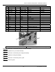
Step 1 : Remove the 20 screws fixing the Mainboard cover 3.
1 = Mainboard cover 3 2 = 2 Screws (M3x6) fixing the Mainboard cover