Active VGA/Audio Balun Kit 500145 (kit), 500146 (TX), 500147 (RX) Installation Guide P/N: 94-000661-A SE-000661-A
© MuxLab Inc. Active VGA/Audio Balun Kit Installation Guide Copyright Notice: Copyright © 2009 MuxLab Inc. All rights reserved. Printed in Canada. No part of this publication may be reproduced, stored in a retrieval system, or transmitted in any form or by any means, electronic, mechanical, photocopying, recording or otherwise without prior written permission of the author. Trademarks: MuxLab and VideoEase are registered trademarks of MuxLab Inc.
© MuxLab Inc. Active VGA/Audio Balun Kit Installation Guide Table of Contents 1. Overview ........................................................................4 1.1. Description........................................................4 1.2. Features.............................................................5 2. Technical Specifications ...............................................6 3. Installation Procedure ..................................................8 3.1. Parts List .........................
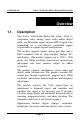
© MuxLab Inc. Active VGA/Audio Balun Kit Installation Guide 1. Overview 1.1. Description The Active VGA/Audio Balun Kit allows VGA or component video, analog stereo audio and/or digital audio, one IR-emitter signal, and one RS232 signal to be transmitted via a cost-effective unshielded copper twisted cable in a point-to-point configuration. The product supports remote power pass-thru and is DDC compliant with all “plug-and-play” laptops, PCs and displays.
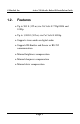
© MuxLab Inc. 1.2.
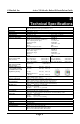
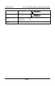
© MuxLab Inc. Active VGA/Audio Balun Kit Installation Guide 2.
© MuxLab Inc.
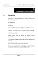
© MuxLab Inc. Active VGA/Audio Balun Kit Installation Guide 3. Installation Procedure 3.1. Parts List The Active VGA/Audio Balun Kit (500145) comes with the following parts: Transmitter Receiver Two (2) External Power Supplies (12 VDC, 0.5 A) Blades for North America, Continental Europe & UK Installation Guide Please verify that all pieces are present before proceeding. VGA & audio jumper cables and Cat 5e/6 cable are not included. RS232 DB9 to DB9 cable are not included.
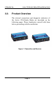
© MuxLab Inc. 3.2. Active VGA/Audio Balun Kit Installation Guide Product Overview The external connections and diagnostic indicators of the Active VGA/Audio Balun are described on the following pages. Please familiarize yourself with them before proceeding with the installation.
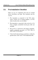
© MuxLab Inc. 3.3. Active VGA/Audio Balun Kit Installation Guide Pre-Installation Checklist There are two (2) components that must be verified before installation can begin: The transmitter and the receiver. 1. The transmitter is connected to the VGA video source, usually a PC or Laptop computer, via VGA video & audio cables (not included). 2. The transmitter is connected to the receiver by a Cat 5e/6 (or higher) unshielded twisted pair cable (not included). 3.
© MuxLab Inc. 3.4. Active VGA/Audio Balun Kit Installation Guide Installation Procedure Verify that the distance between the Active VGA/Audio Balun transmitter and receiver are within MuxLab specifications (see Technical Specifications). In order to install the transmitter, please follow the steps below: 1. Connect the transmitter to the audio-video source with the appropriate VGA video & audio cables. 2. If the Analog Audio (AA) interface is used (Stereo 3.
© MuxLab Inc. Active VGA/Audio Balun Kit Installation Guide 5. Connect a length of Cat 5e/6 (or higher) UTP cable to the transmitter. Ensure that the wiring is in accordance with EIA-568A or EIA-568B standards and is straight-through. Figure 3: Wiring Configuration 6. Connect the 12 VDC power supply to the transmitter. 7. Plug the power supply into an AC power outlet. If power is present, the green power LED will be ON.
© MuxLab Inc. Active VGA/Audio Balun Kit Installation Guide To install the receiver, please follow the steps below: 8. Connect the Active VGA/Audio Balun receiver to the display equipment with the appropriate VGA video & audio cables. 9. If the Analog Audio (AA) interface is used (Stereo 3.5 mm), toggle the Audio switch to the “AA” position. If the Digital Audio (DA) interface is used (RCA), toggle the Audio switch to the “DA” position. Figure 4: Position of the Audio Switch on the receiver 10.
© MuxLab Inc. Active VGA/Audio Balun Kit Installation Guide 12. Connect the UTP cable to the Video IN/UTP connector of the receiver. 13. Connect the second 12 VDC power supply to the receiver. 14. Plug the power supply into an AC power outlet. If power is present, the green power LED will be ON. 15. The brightness rotary switch adjusts the luminance level to compensate for low frequency signal loss due to the Cat 5e/6 cable. 16.
© MuxLab Inc. Active VGA/Audio Balun Kit Installation Guide 19. The following table provides suggested rotary switch settings for adjusting picture brightness. Brightness Setting Less None Medium High Actual Gain -25% 0% 25% 50% Table 1: Rotary Switch Settings for Brightness Adjustment 20. To adjust picture sharpness, begin with the sharpness potentiometer (“Sharp”) rotated completely counterclockwise, and slowly rotate it in the clockwise direction until picture details become clear.
© MuxLab Inc. Active VGA/Audio Balun Kit Installation Guide 21. After sharpness and brightness have been adjusted, adjust the skew in order to align the red green and blue bars. To do this, open the electronic version of this manual and look at the skew correction pattern on the screen (see Figure 6). The R G B potentiometers adjust the red, green and blue colors horizontally. Using the potentiometer, move the three colored lines so they align perfectly.
© MuxLab Inc. Active VGA/Audio Balun Kit Installation Guide 22. Shown below are three typical configurations.
© MuxLab Inc. 3.5.
© MuxLab Inc. Active VGA/Audio Balun Kit Installation Guide 4. Troubleshooting The following table describes some of the problem symptoms, the probable causes and possible solutions. If the information below does not solve the problem, the technical support contact information can be found at the end of this section.
© MuxLab Inc. Active VGA/Audio Balun Kit Installation Guide When contacting your nearest MuxLab dealer or MuxLab Technical Support, please have the following information ready: Unit model number. Cabling layout. Include model of PC and display used, cable length and type. Description of problem. List of tests performed.
© MuxLab Inc. Active VGA/Audio Balun Kit Installation Guide 5. Product Warranty Policy Items Under Warranty - Company Policy MuxLab guarantees its products to be free of defects in manufacturing and workmanship for the warranty period from the date of purchase. If this product fails to give satisfactory performance during this warranty period, MuxLab will either repair or replace this product at no additional charge, except as set forth below.
© MuxLab Inc. Active VGA/Audio Balun Kit Installation Guide Warranty Periods Any product found to be defective within three (3) months of invoice, including one (1) month shelf life, may be returned for replacement by a new unit or a satisfactory repair within one (1) month of receiving any returned product. The customer must provide MuxLab with the serial number and proof of purchase of the defective unit being returned. All R.M.A.
© MuxLab Inc.
© MuxLab Inc. Active VGA/Audio Balun Kit Installation Guide MuxLab Inc. 8495 Dalton, Montreal, Quebec H4T 1V5 Canada Tel.: +1 (514) 905-0588 Fax: +1 (514) 905-0589 Toll Free (North America): 877 689-5228 URL: www.muxlab.com E-mail: videoease@muxlab.