
Users Manual


SOTL5 Monitor IO
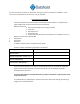
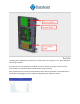
There are 8 inputs in 2 terminal blocks of 4 each. Each block has its own reference. The figures
below show an example pull sheet, but it can be wired in any combination that works for the car
it's installed on. Each block supports one logic circuit supply from 24 – 120 v ac or dc. Low
voltage monitoring (below 60 volts) is accomplished with a jumper installed on a 2 pin
header in front of the wire terminal The unit is powered by 100-240 vac from the cartop as
well.
All wires into the box should be 18 – 20 ga. Stranded.
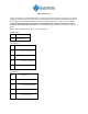
Power Block
Pin1
Neu
Pin5
100-240 vac
Input Block 1
Pin1
Common
Pin2
Power - Logic Feed
Pin3
Inspection
Pin4
Door Zone (optional)
Pin5
Fire Service (optional)
--
Input Block 2
Pin6
Common
Pin7
Interlock or Gate switch
Pin8
Independent (optional)
Pin9
Door Open Limit
Pin10
Door Close Limit