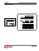
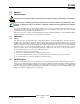
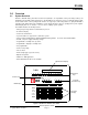
D10024 Analog Fire Alarm Control Panel Operator’s Guide D10024 System Reset Trouble Silence Alarm Silence Manual Alarm YES NO ENTER Letters Numbers Keyword POWER SYSTEM TROUBLE TROUBLE SILENCED ALARM SILENCED POINT BYPASSED ALARM System Reset Trouble S ilen ced Alarm Silence Manual Al arm Enable Keypad Disable Keypad 1 2 3 4 5 6 7 8 9 10 11 12 13 14 15 16 17 18 19 20 21 22 23 24 25 26 27 28 29 30 31 32 33 34 35 36 37 38 39 40 41 42 43 44 45 46
D10024 This page is intentionally blank.
D10024 Contents Contents 1.0 Notices ................................................................................................................................................................................. 5 1.1 General Notices .................................................................................................................................................................... 5 1.2 FCC Notice .............................................................................................
D10024 Figures and Tables Figures Figure 1: D10024 Fire Alarm Control Panel ....................................................................................................................................... 7 Figure 2: D10024 Controls and Displays ........................................................................................................................................... 9 Figure 3: Control Level 2, Entry Menu 1 .............................................................................
D10024 Notices 1.0 Notices 1.1 General Notices These instructions contain procedures to follow in order to avoid personal injury and/or damage to the equipment. NFPA 72 requires a complete system-wide functional test be performed following any modifications, repair, upgrades or adjustments made to the system’s components, hardware, wiring, programming and software/ firmware.
D10024 Notices Notes: 46521C D10024 Operator’s Guide Page 6 Copyright © 2001 Radionics
D10024 Overview 2.0 Overview 2.1 System Overview Radionics’ D10024 Analog Fire Alarm Control Panel (FACP) is an expandable control panel that provides point identification through addressable analog devices. The D10024 has five expansion slots to accommodate plug-in polling circuit modules. Each of these polling circuit modules can support up to 126 analog addresses, giving the D10024 a potential of 630 addressable points.
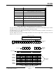
D10024 Overview 2.2 Control Level Distinction The D10024 has three available control levels. At all three levels, the LED display indicates condition, the Zone/Area LEDs indicate location and determined alarm/trouble information is displayed alphanumerically. • Control Level 1 (Display Level): Inhibits the system control keys, limiting the front panel function to annunciation. • Control Level 2 (Controller Level): Allows system control for Fire Drill, Alarm Silence, Trouble Silence and System Reset.
D10024 Overview Key Label Function Shift Shows user options on the alphanumeric display Used in programming to allow letter N to Z. 0, 1, 2, 3, 4, 5, 6, 7, 8, 9 Number keys for digits 0 to 9. >< Scrolls through fires/faults on the alphanumeric display. Letters/Numbers Toggles the alphanumeric keys between letters and numbers. Change Changes a display option. Enter Enters the selection. No Press to answer No or terminate an option. Yes Press to answer Yes or step through an option.
D10024 Overview System Event and Status LED Alarm Function An input point is in alarm state, or has latched into an alarm state. This clears when the system is reset. System Trouble There is a fault in the system: SLC wiring, power fault, etc. This clears when the fault has been corrected and the panel has been reset. Trouble Silenced The annunciation of a fault condition has been manually silenced by an operator.
D10024 Control Level 1 3.0 Control Level 1 (Display Functions) At Control Level 1, the control keys are disabled and the control panel functions only as an annunciator. Pressing any of the control keys will result in a series of interactive messages on the alphanumeric display that end in a prompt for a Control Level 2 passcode. The following subsections explain the features options of Control Level 1. 3.
D10024 Control Level 1 Notes: 46521C D10024 Operator’s Guide Page 12 Copyright © 2001 Radionics
D10024 Control Level 2 4.0 Control Level 2 (Controller Functions) At Control Level 2, the control panel functions as a Controller (see Section 2.2 “Control Level Distinction”). To enable the control keys (to enter Control Level 2), press the [Shift] key. The alphanumeric display shows the following prompt: [Panel ACTIVE control keys INHIBITED] [1] Do you want to enable the control keys? Figure 3: Control Level 2, Entry Menu 1 Press the [Yes] key to enable the control keys.
D10024 Control Level 2 4.2 Trouble Conditions The system responds to other-than-normal conditions that are not caused by alarms by sounding the internal buzzer and initiating a Trouble Condition. 4.2.1 Trouble Signals If a device fails to respond, is disabled, the response is not within the normal parameters, or the system detects a fault, the amber System Trouble or Fault LED will light.
D10024 Control Level 2 4.4 System Operation (Main Menu Options) Pressing the [Shift] key from the normal display will open the Main Menu on the alphanumeric display. The first option, 1) Commission, is not available to Control Level 2 Operators. See the Analog Fire Alarm Control Panels Programming Guide (P/N: 38789) for commissioning and programming information. The other options on the Main Menu permit tests and the setting, enabling and disabling of various system functions.
D10024 Control Level 2 Test from zone? (key in number, then press “Enter’) Figure 10: Zone Test Menu 2 Enter the number of the first zone to be tested and press [Enter]. The panel will then display Zone Test Menu 3.
D10024 Control Level 2 4.4.2 Time Setting Select 3) Time from the Main Menu to change the time displayed on the D10024. 4.4.3 Enable/Disable Functions Main Menu option four, 4) Enable, opens the Enable Menu. Main Menu option five, 5) Disable, opens the Disable Menu.
D10024 Control Level 2 4.4.3.4 Enable/Disable Delayed Day Mode The Delayed Day Mode is configured from Control Level 3. This mode causes the panel to respond to high sensor signals by sounding the panel buzzer and displaying a warning message at the alphanumeric display. The panel delays alarm activation for a programmed period. Configuration parameters allow variations in time of day and zones affected.
D10024 Control Level 2 4.4.4 Print Functions To enter the Print Menu, select 6) Print from the Main Menu. This menu controls the operation of the front panel printer (if installed). PRINT: 1) Devices 2) Events 5) Disabled 3) Mode 4) Setup Figure 17: Print Menu 4.4.4.1 Print Devices This option allows the operator to print out the current state and the text assigned to all devices on a polling circuit (loop). 4.4.4.
D10024 Control Level 2 4.4.5.4 View Outputs This option displays information on the outputs. Using the Alarm Silence Key forces all NAC devices to an OFF condition. 4.4.5.5 View Disablements This option displays information on disabled devices. Select 1) Zones to view disabled devices by zone. Select 2) Inputs to view disabled input devices. 4.4.5.6 View System Events This option displays information on system events. Use the [<] [>] keys to scroll through the events.
D10024 Control Level 3 5.0 Control Level 3 (Programmer Functions) Note: Commission, configure, networking and certain disable options are not available to Control Level 2 operators. These options are reserved for Control Level 3 operators. See the Analog Fire Alarm Control Panels Programming Guide (P/N: 46482) for complete information on commissioning and programming the D10024 Analog FACP. 5.1 Enable/Disable Sounders (NAC Devices) All sounders (NAC devices such as horns, bells, strobes, etc.
D10024 Control Level 3 Notes: 46521C D10024 Operator’s Guide Page 22 Copyright © 2001 Radionics
D10024 Index Index A Alarm Signal Response .............................................. 14 Alarm Signals ............................................................... 14 Alphanumeric and Program/Interactive Key Functions 9 C Conditions Alarm Conditions ..................................................... 11, 14 Power Conditions .................................................... 11, 13 Trouble Conditions .................................................. 11, 14 Control Key Functions .................
© 2001 Radionics, a division of Detection Systems, Inc.