
User manual

myEthernet Referenzkarte / reference sheet 47/48
www.myAVR.de © Laser & Co. Solutions GmbH – 06/2009 www.myAVR.com
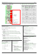
9 Referenzkarte - Pin-Belegung
9 Reference sheet - pin configuration
Pin-Nr. /
Pin
number
mögliche
Konfiguration
possible
configuration
Sonder-
funktion /
special
function
PIN am / on
ATmega644P
0 in,out,analog-in A4
1 in,out,analog-in A5
2 in,out,analog-in A6
3 in,out,analog-in A7
4 in,out B0
5 in,out B1
6 in,out B2
7 in,out B3
8 in,out spi B4
9 in,out spi B5
10 in,out spi B6
11 in,out spi B7
12 in,out,analog-in A0
13 in,out,analog-in A1
14 in,out,analog-in A2
15 in,out,analog-in A3
16 in,out twi C1
17 in,out twi C0
18 in,out C2
19 in,out C3
20 out C4
21 out C5
22 in,out uart D0
23 in,out uart D1
Virtuelle Pins
/ virtual pins
:
Pin 200...207 – Temperatursensor LM75 / temperature sensor LM75
Pin 210, 211 – Byteweise Ein- / Ausgabe /
Input / output byte-by-byte
Pin 1000...3999 – SharedRAM
1000...1999 =
Daten byte-weise, ab Adresse 0
/ data byte-by-byte, from address 0
2000...2999 =
Daten word-weise, ab Adresse 0 (nicht Nr. des Word, sondern Adresse im RAM) /
data word-by-word, from address 0 (not number of the word but address in the RAM)
3000...3999 =
Daten dword-weise, ab Adresse 0 (nicht Nr. des DWord, sondern Adresse im RAM) /
Data dword-by-dword, from address 0 (not number of the dword but address in the RAM)
Pin 5000…7999 – SharedEEPROM
5000...5999 =
Daten byte-weise, ab Adresse 0
/ data byte-by-byte, from address 0
6000...6999 =
Daten word-weise, ab Adresse 0 (nicht Nr des Word, sondern Adresse im RAM)
/
data word-by-word, from address 0 (not number of the word but address in the RAM)
7000...7999 =
Daten dword-weise, ab Adresse 0 (nicht Nr des DWord, sondern Adresse im RAM) /
data dword-by-dword, from address 0 (not number of the dword but address in the RAM)
config.cfg
–
Beispiel
/ config.cfg exam
ple
### Webserver / web server ###
ip=192.168.20.63
ipMask=255.255.255.0
port=80
macAddr=2.126.124.2.8.63
### SharedRAM / -EEPROM ###
sharedRamSize=128
sharedEepromSize=128
twiMode=m24c
twiAddr=0xB0
### Startkonfiguration
/ start configuration ###
# myConfigCmd=°<cmd><pin>~<wert>°<cmd><pin>~<wert>° ... /
# myConfigCmd=°<cmd><pin>~<value>°<cmd><pin>~<value >° ...
# Twi-Temperatursensor0 / temperature sensor0 (200 = twi)
myConfigCmd=°c200~0x10°
# Twi-Temperatursensor1
/ temperature sensor1 (201 = twi)
myConfigCmd=°c201~0x10°
# Twi-Temperatursensor2
/ temperature sensor2 (202 = twi)
myConfigCmd=°c202~0x10°
# Analog-Eingang / Input (12 = analogIn)
myConfigCmd=°c12~0x4°
### Funktionen sperren
/ disable functions ###
cmdConfigDisabled=1
cmdChangeDisabled=1
Liste der Konfigurationswerte
und ihre Bedeutung: /
List of the configuration values and
their meaning:
0x1 = digital output
0x2 = digital input
0x102= digital input mit Pullup
0x4 = analog input
0x8 = uart
0x10 = twi
0x20 = spi
0x40 = ByteOut
0x80 = ByteIn
0x180= ByteIn mit Pullup
Beispiele
/ Examples:
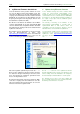
Konfiguration-Beispiel: / Example for configuration:
http://192.168.20.98/?myConfigCmd=°c2~0x1°
Schalt-Beispiel: / Circuit example:
http://192.168.20.98/?myChangeCmd=°o2~1°
Abfrage / Darstellung auf HTML-Seite:
/
Query / presentation on a html file:
°v2°
Temperatursensor
/ temperature sensor:
°v<pinNr>~lm75° =
Temperatur als Dezimalzahl mit Kommastelle
/
temperature as decimal number with decimal place
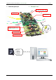
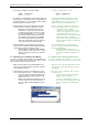
Pin 0
Pin 1
Pin 2
Pin 3
Pin 4
Pin 5
Pin 6
Pin 7
Pin 8 = SS
Pin 9 = MOSI
Pin 10 = MISO
Pin 11 = SCK
5 V
GND
Pin 12
Pin 13
Pin 14
Pin 15
Pin 16 = SDA
Pin 17 = SCL
Pin 18
Pin 19
Pin 20 = LED grün /
LED green
Pin 21 = LED rot /
LED red
Pin 22 = RxD
Pin 23 = TxD
}
UART
}
TWI / I²C
SPI
Statusinformationen: /
Status information:
°i<Parameter>°.
Parameter:
i … IP-Adresse / IP address
n … Netzwerkmaske (Subnet) / network mask
m … Mac-Adresse (hexadezimale Ausgabe)
p … Webserver-Port /
port of the web server
v … Version der Firmware /
version of the firmware
b … Build-Nummer / build number
t … Systemzeit seit Start (Sekunden) /
system time since start (seconds)