
User manual

Seite: 6/7 Technische Beschreibung my7-Segment Add-On 1.0
www.myAVR.de © Laser & Co. Solutions GmbH - 05/2010 www.myAVR.com
Ansteuerung
Programming
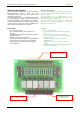
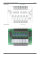
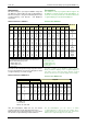
Die Ansteuerung des my7-Segment Add-On erfolgt über
den BCD-zu-7-Segment-Decoder und den Demultiplexer.
Zur Ansteuerung ist es nötig, die Verbindung zwischen der
7-Segment-Anzeige, dem Decoder und Multiplexer
herzustellen.
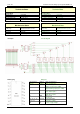
Funktionstabelle des 74HC4511
The activation of the my7-segment add-on happens via
the BCD-to-7-segment decoder and the demultiplexer. To
control it is necessary to make the connection between the
7-segment display, the decoder and multiplexer.
Function Table 74HC4511
INPUTS OUTPUTS
__
LE
__
BI
__
LT
D
4
D
3
D
2
D
1
Q
a
Q
b
Q
c
Q
d
Q
e
Q
f
Q
g
DISPLAY
X X L X X X X H H H H H H H 8
X L H X X X X L L L L L L L blank
L H H L L L L H H H H H H L 0
L H H L L L H L H H L L L L 1
L H H L L H L H H L H H L H 2
L H H L L H H H H H H L L H 3
L H H L H L L L H H L L H H 4
L H H L H L H H L H H L H H 5
L H H L H H L L L H H H H H 6
L H H L H H H H H H L L L L 7
L H H H L L L H H H H H H H 8
L H H H L L H H H H L L H H 9
L H H H L H L L L L L L L L blank
L H H H L H H L L L L L L L blank
L H H H H L L L L L L L L L blank
L H H H H L H L L L L L L L blank
L H H H H H L L L L L L L L blank
L H H H H H H L L L L L L L blank
H H H X X X X
(1)
(1)
1. Ist abhängig vom verwendeten BCD-Code während der
_______ _______
LOW-zu-HIGH
Ü
bertragung von LE.
L = LOW voltage Level
H = HIGH voltage Level
X = Don’t Care
1. Depends upon the BCD-code applied during the LOW-to-
___ ___________ ___-
HIGH transition of LE.
L = LOW voltage Level
H = HIGH voltage Level
X = Don’t Care
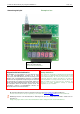
Dem BCD-zu-7-Segment-Decoder übergibt man die Zahl,
die man auf der 7-Segment-Anzeige ausgeben möchte.
Es ist nur sinnvoll Werte von 0 bis 9 zu übergeben, da die
7-Segment-Anzeige sonst nichts ausgibt.
Funktionstabelle des DM74LS138
You give a number to the BCD-to-7-segment decoder
which you want to display on the 7-segment display. It
only makes sense to give them values between 0 and 9
because otherwise the 7-segment display shows nothing.
Function Table DM74LS138
Inputs
Enable Select
Outputs
G1 G2 (Note 1) C B A Y0 Y1 Y2 Y3 Y4 Y5 Y6 Y7
X H X X X H H H H H H H H
L X X X X H H H H H H H H
H L L L L L H H H H H H H
H L L L H H L H H H H H H
H L L H L H H L H H H H H
H L L H H H H H L H H H H
H L H L L H H H H L H H H
H L H L H H H H H H L H H
H L H H L H H H H H H L H
H L H H H H H H H H H H L
H = HIGH Level
L = LOW Level
X = Don’t Care
Note 1: G2 =G2A+G2B
Über den Demultiplexer wählt man aus, auf welcher
7-Segment-Anzeige man die Zahl darstellen möchte.
Dabei werden die 7-Segment-Anzeigen von vorn gezählt,
d.h. die linke 7-Segment-Anzeige hat die Nummer 0.
Via the Demultiplexer you can choose on which
7-segment display you want to have the number. The 7-
segment displays are counted from the front. That means
that the left 7-segment display has the number 0.