CHALLENGE TITAN 200 PAPER CUTTER Instruction Manual Serial Numbers 032425 & Up Provided By http://www.MyBinding.com http://www.MyBindingBlog.
Serial Numbers 032425 & Up OPERATIONAL AND PARTS MANUAL TITAN 200 PAPER CUTTING MACHINE Sold and Serviced by The Challenge Machinery Company 6125 NortonCenter Drive Norton Shores, MI 49441-6081 USA ChallengeMachinery.com F.
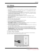
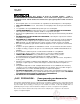
1.0 Introduction 1.0 Introduction THIS MANUAL is designed to help you get the most from your Challenge equipment. Keep this manual in a safe, convenient place for quick reference by operators and service personnel. SAFETY ALERT! This symbol means CAUTION: Personal safety instructions! Pay special attention to the instructions in bold type. Personal injury may result if the precautions are not read and followed.
1.0 Introduction TABLE OF CONTENTS 1.0 Introduction ...................................................................................................................................... 2 2.0 Safety ............................................................................................................................................... 5 2.1 Precautions.................................................................................................................................. 5 2.
1.0 Introduction 6.12.4 Language .......................................................................................................................... 27 6.13 Job Mode.................................................................................................................................. 28 6.13.1 Lock/Unlocking a Job........................................................................................................ 28 6.13.2 Copying a Job .................................................
2.0 Safety 2.0 Safety 2.1 Precautions • • • • • • • • • • • • • • • • This machine is designed for one-person operation. Never operate the machine with more than one person. Safe use of this machine is the responsibility of the operator. Use good judgment and common sense when working with and around this machine. Read and understand all instructions thoroughly before using the machine. If questions remain, contact the dealer from which you purchased this machine.
2.0 Safety 2.3 Warning Label Definitions The following warning labels are found at various locations on your machine. Read and understand the meaning of each symbol. If a label is lost from the machine, it should be replaced. HAZARDOUS AREA Disconnect power before cleaning, servicing, or making adjustments not requiring power. Do not alter safety guards or devices; they are for your protection. Replace all guards. Do not operate with any guards removed.
2.0 Safety !OJO! This Este simbolo de alerta de seguridad significa ¡ OJO ! INSTRUCCIONES DE SEGURIDADPERSONAL. Lea las instrucciones porque se refieren a su seguridad personal. Fall de obedecer las instrucciones que siguen podria resultar en lesiones corporales. • • • • • • • • • • • • • • • • • • • • Esta maquina, junto con sus mecanismos de seguridad, esta disenada para ser manejada por UNA SOLA PERSONA a la vez. Jamas debe ser manejada por mas de una persona al mismo tiempo.
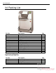
3.0 Packing List 3.0 Packing List Part No. A-10034 4166 F.200-C A-12608-2 20-2150-2 H-6918-608 8815 5064 43108 W-130 W-137 W-164 W-170 SU-10-113 Description Knife Cutting Stick (in addition to one installed in machine) Instruction and Parts Manual Jogging Aid Tool Kit Knife Bolts, 3/8 – 16 x 1” Knife Washers, Special Cutting Stick Puller Knife Lifter Assembly 3/16” Allen Wrench 5/32” Allen Wrench 5/16” Hex ‘T’ Wrench 9/16 x ½” Wrench Grease Brush Qty. 2 3 1 1 1 4 4 1 1 1 1 1 1 1 Optional Items Part No.
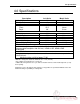
4.0 Specifications 4.0 Specifications Description Inch Units Metric Units Cutting Width 20” 51 cm Minimum Cut* ½” 13 mm Clamp Opening 3 ¼” 8 cm Table Space Front: 15¼” 39 cm Back: 20” 51 cm Dimensions Table Height 36” 91 cm Overall Height 53” 135 cm Overall Length*** 49” 124 cm Overall Width 36” 91 cm Approx. Net Weight 800 lbs 361 kg Approx. Shipping Weight 920 lbs 418 kg Electrical 208/230 Volts, 12 Amps, 1 Phase, 60 Hz, AC.
5.0 Installation & Setup 5.0 Installation & Setup 5.1 Inspecting Shipment This machine has been carefully packed to prevent damage during shipment. However, claims for damage or loss are the responsibility of the recipient. Inspect all shipments as soon as they are received. If there is any noticeable damage, note it on the freight bill. Visual and/or hidden damage must be reported to the claims department of the carrier within 15 days. Contact your dealer if you need any assistance.
5.0 Installation & Setup Figure 3 5.3 Cleaning After unpacking, wipe down all machine panels and clean the table surface. 5.4 Fitting Through Narrow Door The Titan 200 cutter will not fit through an opening less than 36” (91 cm) without the table being removed. With the table removed, the Titan 200 will fit through a 35” (89 cm) opening. With the table, front guard, and foot treadle removed, it will fit through a 28” (71 cm) opening. 5.4.
5.0 Installation & Setup Encoder Plug Rear Support Leg Figure 4C Remove the motor junction box cover and disconnect the wires to the motor (Figure 5). Remove the leadscrew cover and the nylon tyraps that are attached to the bottom of the table. The motor wires and encoder wires should now be free from the table. Motor Junction Box Cover Figure 5 From the rear of the machine, remove the presetter board assembly from the table (Figure 6 on page 13).
5.
5.0 Installation & Setup 5.4.2 Removing the Foot Treadle Make sure the power is off and the power cord is disconnected. Remove the lower front cover. Use an open-end wrench to remove the two cables attached to the base, which hold up the foot treadle. Carefully, remove the springs. Now remove the pins at the rear pivot points of the foot treadle. Remove the treadle. 5.4.3 Removing the Front Guard (If Equipped) Make sure the power is off and disconnect the power cord. Open the front guard.
5.0 Installation & Setup 5.5 Installing Optional Extension Tables (Front Guard Machines Only) Using the wood screws provided, attach a back plate to each extension table. Using (4) 3/8-16 capscrews, attach the table support to the under side of the main table as shown in (Figure 11). Route each cut button wire through the slots in the bracket and relocate the cut buttons to the extension tables (as shown).
5.0 Installation & Setup Dip Stick Figure 12 5.7 False Clamp Plate (Optional) To prevent marking on pressure sensitive jobs, a false clamp plate is available as an optional item for your machine. This plate attaches to the bottom of the clamp. It is secured with wing nuts on studs that pass through the top of the clamp. To install: 1. Make sure the knife and clamp are in the up position.
5.0 Installation & Setup 5.8 Power Hook-Up SHOCK HAZARD! NEVER CUT THE GROUND PLUG from a three-prong plug to fit a two-prong socket. Possible shock could cause personal injury or death. Hire a qualified electrician to provide a power source that meets electrical requirements and all local electrical codes. It is the customer’s responsibility to provide a properly grounded receptacle that meets the power requirements specified on the nameplate of this machine, as well as all local electrical codes.
5.0 Installation & Setup Line Light Adjustment Screw Figure 15 5.9.1 Adjustment 1. Place a wide sheet of paper on the cut stick to view the line light. 2. Using a 3/16” hex allen wrench, turn one of the cap screws until you see a 1/16-1/8” beam. Note: it is best to start by turning the screw clockwise. If the screw turns all the way in before a line appears, begin turning the screw counterclockwise. 3.
6.0 Operation 6.0 Operation IMPORTANT: DO NOT ATTEMPT TO OPERATE THE CUTTER UNTIL YOU HAVE THOROUGHLY READ AND UNDERSTAND ALL OF THE FOLLOWING INSTRUCTIONS. CALL YOUR AUTHORIZED CHALLENGE DEALER IF YOU STILL HAVE ANY QUESTIONS. 6.1 Power – Main Switch Power is brought to the machine when the main power switch is turned to the “ON” position (Figure 16). The display and line lights are turned on at this time.
6.0 Operation 5.000 in >_ A) Maint B) Job The backgauge may now be sent to a desired position by simply typing the dimension and pressing SEND (see the Send Mode section, page 24, for more details). 6.3 Making a Cut (Machines With Electric Eyes) Place the paper against the backgauge and left side guide. Note: If the cut will leave strips of paper less than 1/2” wide, place the paper against the right side guide.
6.0 Operation Figure 17 Figure 18 6.6 Knife Change Alarm and Lubrication Alarm The Titan 200 has two built in alarms that will be displayed after a certain number of cuts. The knife alarm displays a message that notifies the operator to change the knife. The lube alarm displays a message that notifies the operator to have the machine lubricated. The lube alarm will also display the name and phone number of the Challenge dealer from which the machine was purchased.
6.0 Operation 6.8 Display Panel Display SEND Key IN/MM Key Variable Speed Pinpoint Backgauge Control Soft Keys Push-Out Key Arrow Keys Priority Add (X/Y) Key ENTER Key CLEAR Key Figure 19 6.9 Definition of Keys 6.9.1 Variable Speed Pinpoint Backgauge Control The backgauge control is used to manually position the backgauge. The speed of the backgauge will depend upon where the actuator is pressed. Press farther from center for a faster speed.
6.0 Operation 6.9.4 Push-Out Key/Hold-To-Run Backgauge Key This key has 2 functions. It is used to move the backgauge forward 5 inches (or to the most forward position) and then return it to its previous position. This allows paper to be removed from the cutter without putting hands under the knife and clamp. It also allows backgauge to move forward under program control if the electric eyes are blocked (or front guard is raised) for dimensions less than 3.5 inches (8.9 cm).
6.0 Operation 6.10.2 Backlash Indicator To insure accurate cuts, the backgauge must be brought to the cut position from the rear of the table. In the display, to the right of the backgauge position, there is a small arrow to indicate reverse travel (Figure 20). This arrow should be off when making a cut. Moving back past your cut position, then forward to it, compensates for any play in the backgauge nut and leadscrew. 6.11 Send Mode 5.
6.0 Operation 6.12 Maintenance Mode The maintenance mode is an area where many machine functions can be set or modified. The four principle functions are: Language, Parameters, Diagnostic, and Knife Adjust. From the Send Screen, (Figure 20 on page 24), enter “A” to go to the Maintenance Screen. To select a particular function, use the up and down arrow keys to toggle to the desired function and press ENTER. See the following descriptions for an explanation of each function. 5.
6.0 Operation this feature off. It is recommended that this feature be left on whenever possible. In the push-out screen, use the up and down arrow keys to toggle to the on or off status as desired, and press ENTER. 6.12.2.4 Accuracy Adjust This parameter provides a means for adjusting the accuracy of the backgauge. To change the accuracy, send the backgauge to 2 inches (50.8mm) and cut some paper. Measure the paper, and type in what you actually measure.
6.0 Operation 6.12.3 Diagnostic The diagnostic area can be very helpful in locating a problem in the event of a machine malfunction. Use the up and down arrow keys to toggle to the desired selection, and press ENTER. See the following descriptions for an explanation of each. 5.000 in DIAGNOSTIC Error Code Sensor Data Clear Memory Electric Clamp Clamp Adjust A) Maint B) Job C) Send D) Exit 6.12.3.1 Error Code The Error Code function simply recalls the last five error messages that were displayed.
6.0 Operation 6.13 Job Mode The Titan 200 can be programmed for up to 99 different jobs or channels. A job is used for making a sequence of cuts using the send (or cut) values of the job as the backgauge positions for each cut. Each job can hold up to 99 send values. If 2 channels are linked, up to 198 send values can be accessed from one job. When the job mode is entered, all previously programmed jobs will be displayed along with their name and lock status.
6.0 Operation simply press ENTER again to begin entering send values (see below). To name the job, press the right arrow key to move the cursor to the first character position. Enter a character of the alphabet by using the up and down arrow keys to toggle to the desired character. The numeric keys can be used to enter numbers directly into the job name. When the desired character is in place, use the right arrow key to move to the next character position. The job name can be up to 10 characters long.
6.0 Operation To unlink a job, use the up or down arrow key to point to the linked job name and press soft-key “C” (Erase). When finished entering send values you may exit the current job by pressing soft-key “B” (Job) to go back to the job mode screen or soft-key “D” (Exit) to exit to send mode. Or you may use the current job for cutting by pressing the down arrow at the last line and following the instructions in the Running a Programmed Job section 6.13.6 below. 6.13.5 Editing an Existing Job 6.13.5.
6.0 Operation position. After the last cut in the job is made, the backgauge will move to the first cut position of the current job. Pressing SEND at any time during the job will send the backgauge to its next programmed position without making a cut. A plus “+” sign will be displayed at the bottom of the screen if more cuts remain in the current job. 6.13.
6.0 Operation Now press ENTER to begin programming the job. The display should now look similar to the one shown next: 5.000in #7 1> _ A) Insert B) Job C) Erase D) Exit 4. To enter the first send value of 8.5”, simply type in 8.5 and press ENTER. The cursor will move to the second line. Now type 11 and press enter. 5.000in # 7 1> 8.500 2> 11.
6.0 Operation 6.15 Operating Tips Carefully lay out each sheet before you start cutting. Find the best cut pattern to give you the most pieces out of the sheet. If the sheet will be folded, be sure grain of the paper is running in the same direction as the fold or you will get a rough edge on the fold. If an accurate cut is necessary for close register work, you MUST have a sharp blade in the cutter. A dull blade will pull or draw the paper and cause uneven cutting.
7.0 Knife Installation/Changing 7.0 Knife Installation/Changing Changing knives can be very dangerous unless safety precautions are observed and extreme care is taken when handling knives. • • • • • • Make sure knife lifters are properly installed, see instructions following. Keep handling of unprotected knives to an absolute minimum. Clear off cutter table before removing knife. Have scabbard on cutter table and insert knife immediately. Warn people of any unprotected knife.
7.0 Knife Installation/Changing Knife Adjusting Screws Figure 22 3. Remove the knife bolts from the two slotted knife bar holes and replace with the knife lifter assembly (Figure 23). Tighten the lifters to hold the knife in place, and then remove the remaining two knife bolts. Figure 23 4. Clear the table surfaces and place the empty knife scabbard on the table. scabbard’s knife retaining screws. Remove the 5.
7.0 Knife Installation/Changing 7.2 Knife Installation Knives are heavy and always very sharp! Be sure to keep the edge away from your body and keep other people out of the area while handling the blade. Severe lacerations or dismemberment could result from careless handling procedures. 1. Make sure the knife and clamp are in the up position. If they are not, turn on the power using the red and yellow main power switch, close the front guard (if equipped), and press the CLEAR button.
7.0 Knife Installation/Changing Figure 25 14. Plug in the power cord and turn the power on. 15. Close the front guard (if equipped) and press CLEAR. This will raise the knife and clamp to the up position. 16. Turn the power off and disconnect the machine power cord. 17. Tighten all knife bolts securely. 18. Plug in the power cord and turn the power on. Make a test cut through a full lift of paper and make minor adjustments if necessary by repeating steps 9 through 17.
7.0 Knife Installation/Changing determine when the knife blade needs to be sharpened. Some characteristics that indicate a blade needs sharpening are: • The knife hesitates or stalls while making a cut. • The sheets are not all cut to the same length (usually the top few sheets are longer than the rest of the sheets - this is sometimes called “draw”). • Cut marks appear on the cut face of the paper. • The profile of the cut (side view) is not perpendicular to the table.
7.0 Knife Installation/Changing • If a knife bolt is damaged, replace it. • Always keep knife bolts securely tightened. • Always use the heavy duty knife bolt washers provided by Challenge. Failure to do so could result in scratching or marring of the clamp face. • Store knives in a dry environment to prevent corrosion. • Never attempt to service a knife in any way.
8.0 Maintenance Guide 8.0 Maintenance Guide NOTICE The instructions on the following pages are for the use of trained service personnel only! Attempting to perform repair and replacement procedures without proper training may cause machine damage or operator injury! PARTS CUSTOMERS: Parts with the express understanding that they are to replace parts found missing or no longer serviceable on equipment designed and/or manufactured at Challenge.
8.0 Maintenance Guide 8.1 Routine Maintenance DISCONNECT POWER before making any adjustments or lubricating. See page 5, SAFETY PRECAUTIONS, for Power Lockout Procedure. This machine should be placed on a regular maintenance schedule. A clean, lubricated machine will run longer, smoother, cut more accurately, with less downtime and fewer costly repairs. Schedule lubrication both early in the day and early in the week. This allows the lubricants to work into the machine.
8.0 Maintenance Guide Fluid level should be at 1/8” from the end of the dip stick (check with dip stick cap screwed in). Add fluid if necessary but avoid overfilling as this could cause leakage when hot. Replace the rear panel when finished. The hydraulic fluid should be changed AT LEAST ONCE-A-YEAR or after every 1,000 hours of operation. NOTE: Failure to change oil when needed can damage seals in the cylinders, pump, and valves.
8.0 Maintenance Guide Grease Oil Figure 27 – Knife Bar Link – L.H. Side, Upper Figure 28 – Knife Bar Link – R.H.
8.0 Maintenance Guide Figure 30 – Knife Bar Link – L.H. Side, Lower Figure 31 – Knife Bar Link – R.S.
8.0 Maintenance Guide Figure 34 – Leadscrew and Backgauge Guide 8.4 Adjustments Several of the following tests require the machine to be operational for checking and adjusting. Be very careful that tools and other people are clear of moving parts and that the cutter is not accidentally operated while adjustments are being made. Whenever working on the machine, disconnect the power and lock it out (see SAFETY PRECAUTIONS, page 5) unless the directions specifically require the machine to be powered. 8.4.
8.0 Maintenance Guide Gib Screws Nylon Guide Screws Figure 35 5. Tighten the bottom, nylon guide screws until they just touch the guide. Do not overtighten or they could cause the backgauge to bind. 6. Similarly, turn the side gib screws in until they just touch the guide. Lock in position with the jam nuts. 7. Run the backgauge back and forth the length of the table using the backgauge glide control. Check for any binding. Readjust if necessary.
8.0 Maintenance Guide Adjusting Screws with Jam Nuts Figure 37 4. Back off the adjusting screw on the side that the trim occurred and tighten the other. 5. With the squaring screws tight, make another test. Continue to adjust and test until no trim occurs when testing either sequence. 6. Replace the rear plexiglass table cover. Note: Once the backgauge is square, restore power to the machine and check the backgauge accuracy (see section 6.12.2.4 on page 26) to make sure it is accurate. 8.4.
8.0 Maintenance Guide DO NOT set the clamp pressure below 400 psi. Severe lacerations or dismemberment could result! The knife and clamp system loses sequence at settings below 400 psi and the knife could come down before the clamp. 8.4.4.1 Optional Electronic Clamp Pressure Control Adjustment The electronic clamping control option allows the convenience of changing the clamp pressure at the control console.
8.0 Maintenance Guide 8.5 Cleaning Before cleaning inside machine, turn off and lockout power, page 5. Hydraulics 1. The vent fan should be wiped off weekly to maintain maximum cooling of the hydraulic system. 2. The hydraulic manifold, fittings, and hoses should be wiped off weekly to maintain maximum cooling. Remove then replace panels as necessary. Table 1. The front table should be wiped down periodically. Use a non-abrasive cleaner along with a protective wax. 2.
9.0 Schematics & Parts Lists 9.0 Schematics & Parts Lists 9.1 Main Assembly – Front View 43000 Sht. 1 of 4, Rev.
9.0 Schematics & Parts Lists Main Assembly – Front View – 43000 Sht. 1 of 4, Rev.
9.0 Schematics & Parts Lists 9.2 Main Assembly – Right Side View 43000 Sht. 2 of 4, Rev.
9.0 Schematics & Parts Lists Main Assembly – Right Side View – 43000 Sht. 2 of 4, Rev.
9.0 Schematics & Parts Lists 9.3 Main Assembly – Table Asm. View 43000 Sht. 3 of 4, Rev.
9.0 Schematics & Parts Lists Main Assembly – Table Asm. View – 43000 Sht. 3 of 4, Rev.
9.0 Schematics & Parts Lists 9.4 Main Assembly – Tilt Shield / Electric Eyes 43000 Sht. 4 of 4, Rev.
9.0 Schematics & Parts Lists Main Assembly – 43000 Sht. 4 of 4, Rev.
9.0 Schematics & Parts Lists 9.5 Hydraulic Power Unit – 60 Hz H-477-1, Rev.
9.0 Schematics & Parts Lists 9.6 Hydraulic Power Unit – 50 Hz H-477-2, Rev.
9.0 Schematics & Parts Lists 9.
9.0 Schematics & Parts Lists 9.8 Power Panel Label S-1781-54, Rev.
9.0 Schematics & Parts Lists 9.9 Power Panel Assembly EE-2765-1, Rev.
9.0 Schematics & Parts Lists Power Panel Assembly – EE-2765-1, Rev.
9.0 Schematics & Parts Lists 9.10 Control Console Assembly EE-3035, Rev.
9.0 Schematics & Parts Lists 9.11 Knife Latch Assembly 41120-3, Rev.
9.0 Schematics & Parts Lists 9.12 Line Light Assembly EE-2779, Rev.
9.0 Schematics & Parts Lists 9.13 Cut Button Assembly EE-2851-3 Rev.
9.0 Schematics & Parts Lists 9.14 Fuse Value and Function Location F1 Transformer/Voltage 230 VAC Dimension 5mm x 20mm F2 F3 F4 Fuse Value/Type Circuit 2A-T Backgauge Motor 3.15A-T Pcb output 5A-T Line Lights 10A-T Main – Hot T1.Secondary 12 VDC 230 VAC F5 .5A-T T2 Primary 5mm x 20mm 5mm x 20mm 13/32” x 11/2” ¼” x 1-1/4” F6 1.25A-T T1 Primary ¼” x 1-1/4” F7 10A-T 230 VAC FL 5A-T 13/32” x 11/2” 5mm x 20mm T = Time Delay Fuse 68 5V-logic, preset, encoder/15vprox.
9.0 Schematics & Parts Lists 9.15 Control P.C.
9.0 Schematics & Parts Lists 9.16 Electric Eye Assembly K-3030 Sheet 1, Rev.
9.0 Schematics & Parts Lists Electric Eye Assembly – K-3030 Sheet 1, Rev.
9.0 Schematics & Parts Lists Electric Eye Assembly – K-3030 Sheet 2, Rev.
9.0 Schematics & Parts Lists Electric Eye Assembly – K-3030 Sheet 2, Rev.
9.0 Schematics & Parts Lists 9.
9.
10.0 Safety Systems Test 10.0 Safety Systems Test Machine manufacturer CHALLENGE Model TITAN 200 Serial Number __________________ Frequency of test: THESE TESTS SHOULD BE PERFORMED AT THE BEGINNING OF EACH WORK DAY. Turn the power on and press CLEAR to preset the backgauge. Make sure the knife and clamp are in the up position (if they are not, follow the instructions in this manual to send them up). Machines with Front Guards: Test #1: With the front guard open, press the cut buttons.
10.0 Safety Systems Test Please enter date and initials for both tests.