
User's Manual


Page 4 of 12
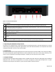
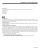
Figure 1.2 Connections of the decoder
How to connect
A
The detection loop: Connect the supplied 75 Ohm double-shielded coax cable to the MYLAPS X2
Prochip
decoder.
B
The auxiliary port: This port can be used to connect a photocell, external start pulse or a sync pulse. For more information on
how to connect these devices, see appendix D.
C
The GPS antenna: Connect the GPS antenna cable and place the antenna where it has a clear view of the sky overhead to be
able to make connections to satellites
D
CAN connector: for future use
E
The network: This port can be used to connect the network cable between the decoder and the network connection port of the
computer.
F
Power: Connect the supplied VDC adapter to the decoder and mains. It is recommended to connect the VDC adapter to mains
through an Uninterruptable Power Supply (UPS) to avoid any interruption of power supply to the decoder.
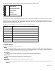
1.2 Operating the MYLAPS X2 Prochip decoder
The decoder is not equipped with an on/off switch therefore connecting the decoder to the mains will switch it on. This will
enable timing of transponder passings after approximately 15 seconds. With each detection of a transponder the received
transponder information is shown on the decoder display.
1.2.1 Noise level
The decoder determines the average background noise. Noise level should not exceed -85 dBm. If the noise level is higher,
the received transponder signal strength should be at least 20 dBm above noise level to ensure proper functioning of the
system. So if the transponder received signal strength is -55 dBm, the noise should not exceed -75 dBm.
1.2.2 Signal strength
Transponder signal strength should preferably be above -65 dBm and should at least be 20 dBm higher than the indicated
background noise. The closer the transponder is to the track, the higher the received signal strength will be. A higher
transponder signal strength should allow for greater immunity against outside interference.