INSTALLATION MANUAL 42” and 60” HAYDEN MP-4 Illustrations are general and may not match your specific stair design.
www.mylenstairs.
IMPORTANT MESSAGE On behalf of everyone at Mylen Stairs, we would like to thank you for your purchase of one of our products. This product is designed and manufactured in the USA. This stair comes with an Installation Manual. It is important that you read and fully understand this manual prior to installation. Following the steps exactly as specified in the manual will ease installation and reduce the amount of time necessary to complete the process.
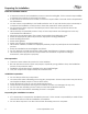
Preparing For Installation Read the Installation Manual If anyone involved in the installation process cannot read English, it is the owner's responsibility to explain the contents of this manual to them. If any portion of this manual is unclear, contact the Mylen Stairs Customer Service Department for clarification. It is the owner’s responsibility to be familiar with the use of any tools that may be necessary to complete the installation of this product.
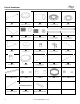
Parts & Hardware ① ② ③ ④ ⑤ Base Baseplate Cover Sleeve Centering Ring Spacer ⑥ ⑦ ⑧ ⑨ ⑩ Tread Threaded Coupler Treaded Coupler w/ nut Column Segment Column Segment (both ends threaded) (one end threaded) ⑪ ⑫ ⑬ ⑭ ⑮ Platform Column Cap Platform Nut Spacer Platform Bracket Platform Rail ⑯ ⑰ ⑱ ⑲ ⑳ Baluster Cup Handrail Platform Rail Post Platform Rail Post Vertical Post (with set screw holes) 5 21 22 23 24 25 Platform Rail Capping Baluster Line Rail Mount Line
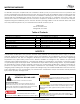
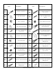
Item 6 Description Item Description #10-32x1-1/2” Flat Head Type F Screw Ⓐ 3/8”x3” Lag Screw Ⓑ 3/8” Flat Washer Ⓝ Ⓒ 5/8”-11 Hex Nut Ⓞ 5/16”-18x5/16” Set Screw Ⓓ 5/8” Structural Washer Ⓟ 5/16”-18x1-1/2” Hex Drive Flat Head Screw Ⓔ 5/16”-18 x 1” Hex Drive Flat Head Screw Ⓠ 5/16”-18x2-1/2” Hex Drive Button Head Screw Ⓕ 5/16”x.
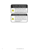
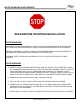
WOOD HANDLING AND FINISHING READ BEFORE STARTING INSTALLATION WOOD HANDLING UNFINISHED TREADS AND HANDRAILS ON THE JOB SITE WILL ABSORB MOISTURE FROM THE AIR. THESE MUST BE SEALED WITHIN 1 WEEK TO AVOID ADVERSE AFFECTS ON THE WOOD. NEARBY PLASTERING, TILE WORK, CEMENT OR BRICKWORK INTRODUCE ENOUGH WATER IN THE IMMEDIATE ENVIRONMENT FOR THE WOOD TO BE AFFECTED. IF NEEDED, STORE THE WOOD PROVIDED IN A COOL, DRY AND STRUCTURALLY STABLE LOCATION. WOOD FINISHING A.
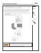
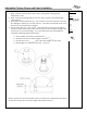
Base Positioning and Installation Hardware 1. Measure the platform from the mounting face to the center of the large hole to determine where to mount the base (1). NOTE: Alternatively, you can lay the platform on the lower floor to get a layout for where the column will fall. This is only possible if the mounting wall(s)/surface(s) extend all the way to the lower floor and are plumb. ⒶⒷ Parts 2. After positioning the base, fasten it to the floor with hardware (A) and hardware (B). 3.
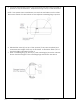
Adjustable Column Sleeve and Tread Installation Hardware 1. Slide a sleeve (3) onto the base column and guide it through the baseplate cover. 2. Slide a Clear centering ring (4) onto the base column with the flanges facing down 3. Most stairs will need spacers (5). The number of spacers can be found by first sliding the tread (6) over the column. Press the tread firmly down onto the sleeve and measure the height. 4. The spacers are 1/8” (.125”) thick.
5. If spacers are required, remove the tread and add the correct number of spacers on top of the sleeve. All spacer must go on top of the first sleeve. NOTE: The spacers have small bosses on one side and indents on the other. The bosses should sit in the indents of the adjacent centering ring or spacer. 6. Reinstall the tread (6) on top of the spacers (if any were required) and remeasure the height of the top of the tread. It should be within 1/8” of the riser height calculated in Step 4. 7.
8. Slide a tread (6) down the column. Press the tread firmly down onto the sleeve and measure the height from the top of the tread to the floor. 9. Because this is the second tread, the height from the floor to the top of the tread should be two times the riser height calculated in Step 4. Calculate how many spacers will be needed under the tread to raise the tread from the measured height (without spacers) to two times the riser height of the stair. 10.
Column Coupler and Column Segment Installation Hardware NOTE: The column comes in segments that are connected with threaded couplers. The column segments with threads in both ends are installed first. The column segment with threads in only one end (10) will be cut to length and installed at the top with the threaded coupler with the nut (8). See below for where to cut the segment. Parts ⑦⑧⑨⑩ Use these items first Tools Use these items last (at the top of the stair) 1.
4. Screw the top column segment in and mark where the top of the platform will be in the column. Typically the top surface of the platform will be flush with the top floor. 5. Measure 4” down from the mark. Remove the top segment and cut at this line. 6. Reinstall the top column segment after cutting it to size. Add the remaining treads. 13 www.mylenstairs.
Platform Installation Hardware 1. Screw the threaded rod (27) into the nut in the column. The threaded rod should protrude approximately 6” up past the top of the column segment. 2. Slide the spacers (5) (if needed) centering rings (4) and sleeve onto the column segment. Use the same number of spacers as the tread below. ⒶⒷⒸⒹ ⒺⒻⒼⒽ Parts ③④⑤⑪ ⑫⑬⑭ 27 Tools Do not install the platform unless the stair is braced. The weight of the platform could cause the stair to become unstable.
5. The platform is reversible and will work with left hand up and right hand up stairs. Identify and mark which side of the platform will be facing up and which side will be facing down. 6. After marking the platform, remove it from the stair and fasten the mounting brackets (14) to the bottom surface in locations shown below. The brackets should be mounted flush to the edge of the platform. For a wood laminate platform drill small 3/16” pilot holes in the locations for the lag bolts (H).
7. For metal platforms, loosely secure the platform mount brackets to the bottom of the platform with hardware (E),(F) and (G). There are pre-drilled holes where the mount brackets should be positioned. 8. With the mounting brackets installed on the bottom of the platform, reposition the platform onto the column. Hold the platform in position and fasten the mounting brackets to the wall using hardware (A) and (B). If needed, 3/16” pilot holes can be drilled for hardware A. 9.
10. Slide the column cap (12) onto the column and through the hole in the platform. Ensure that the column cap is fully inserted and resting flush on the platform. 11. Secure the platform to the column with the platform nut spacer (13) and hardware (C) and (D). There should be between ½” and ¾” of threaded rod above the nut. Spin the threaded rod until it is within this range, then tighten the nut to 25 ft-lbs. This will compress the column and remove any gaps between the treads and column segments.
Line Rail Baluster Installation Hardware 1. Slide a baluster (15) through the platform and tread below. Fasten baluster line rail mounts (22) to the baluster with hardware (X). The line rail mounts will prevent the baluster from falling through the hole in the tread. Plumb the baluster by rotating the tread below before moving to the next baluster. NOTE: Make sure the baluster line rail mounts on the correct side of the baluster for your specific installation.
6. Start at the bottom baluster of the stair and slide the line rail cups (23) onto the lowest line rail mount and partially tighten the set screws closest to the baluster. The set screws should be tight enough to allow the line rail cups to still rotate. 7. Take a coiled section of stainless steel line rail (24) and insert it through the line rail cup installed in Step 6. Tighten the set screws to lock the line rail in place. 8. Slide a line rail cup down the line rail and secure it to the next baluster.
9. Fasten the bottom baluster to the baluster cup using hardware (L). 10. Fasten the balusters to the treads and the platform using hardware (I) for metal treads or hardware (J) for laminate treads. Be sure to push the balusters up until they are flush with the bottom of the tread before installing the hardware. NOTE: Do not install the other line rails at this time. Wait until after the handrail is installed in the next steps before installing the remaining line rails.
Aluminum Handrail Forming Hardware 1. The handrail is shipped in a coil that is typically between 36” and 48” in diameter. The first step to fitting the handrail is increasing this diameter to the proper coil diameter listed below. Stair Diameter Coil Diameter 3’-6” 60” 5’-0” 75” NOTE: The coil diameter should be larger than the stair diameter. 2. On a soft surface such as carpet, position the coil as depicted below. The cut end (1) should be approximately 4”-6” off the ground. 3.
7. Repeat steps 5 and 6 until the cut end is vertical. It should now be long enough to form by hand. 8. Hold the coil in place and pull the unsecured side outward and away from the center of the coil until the coil bends slightly. It may be necessary to brace the coil where it contacts the ground to prevent it from slipping while forming. 9. Continue rotating the coil and forming until the whole coil has been worked through. Measure the coil diameter to determine if more adjustment is needed.
Checking the Handrail Curvature Hardware 10. Lay the handrail down and find the cut end that contacts the ground. Use the method below to determine the orientation of the handrail. Parts ⑪ Tools NOTE: If the handrail orientation matches the orientation of the stairs being installed, skip to the next step. 11. Stand the handrail up. Push a cut end towards the center of the coil enough to clear the adjacent rail. Pull this cut end through the coil to the other side.
Pulling the Handrail into a Spiral Hardware 1. Determine the end to end length needed based on the diameter of the stair being installed. Stair Diameter End to End Length 3’-6” 14’ 5’-0” 11’ 2. With the help of another person, pull the handrail apart to the desired end to end length. Stop periodically to inspect the handrail for any kinks that may be forming. 24 www.mylenstairs.
Aluminum Handrail Installation Hardware 1. Once the Handrail has been shaped, dry fit the rail to the baluster tips. NOTE: The handrail may be slightly kinked on both ends. This is normal and the handrail should be positioned so that these ends can be cut off after installation. 2. With a helper, position the handrail (17) on top of the balusters. 3. Start at the top of the stair. Hold the handrail firmly against the baluster tip.
Platform Rail Installation Hardware 1. Tighten the nut at the top of the column to 85 ft-lbs before proceeding to step 2. Failure to tighten the nut at the top of the column could result in the stair becoming unstable and fall and result in serious injury or death. 2. Thread hardware (O) into the bottom of the platform rail post (18). 3. Secure the platform rail mount plate (28) to the top of the post with hardware (P). The mount plate should sit on top of the notches. 4.
5. Install the platform post without holes (20) into the location next to the top baluster using hardware (Q and R). 6. Place the platform rail capping (21) on top of the posts and secure with hardware (S). 27 www.mylenstairs.
Infill Installation Hardware 1. At this point, the balusters should be fastened to the treads with the handrail and the lowest line rail installed. 2. Start at the bottom baluster of the stair. Slide the rail cups (23) onto the line rail mounts and partially tighten the set screws closest to the baluster. They should be tight enough to where they can still rotate. 3. Take a coiled section of stainless line rail (24) and insert it through the line rail cup.
5. Mount platform rail mounts to the platform posts with hardware (U) similar to Step 1. The platform line rail mounts have a flat bottom. 6. Install the line rail cups (23) to the mounts followed by the straight segments of the stainless line rail. Tighten all the set screws. 7. After all platform line rail is installed, go back through and cut off excess line rail if needed. 29 www.mylenstairs.