INSTALLATION MANUAL 42” and 60” CONDOR MP-2 Illustrations are general and may not match your specific stair design.
www.mylenstairs.
IMPORTANT MESSAGE On behalf of everyone at Mylen Stairs, we would like to thank you for your purchase of one of our products. This product is designed and manufactured in the USA. This stair comes with an Installation Manual. It is important that you read and fully understand this manual prior to installation. Following the steps exactly as specified in the manual will ease installation and reduce the amount of time necessary to complete the process.
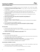
Preparing For Installation Read the Installation Manual If anyone involved in the installation process cannot read English, it is the owner's responsibility to explain the contents of this manual to them. If any portion of this manual is unclear, contact the Mylen Stairs Customer Service Department for clarification. It is the owner’s responsibility to be familiar with the use of any tools that may be necessary to complete the installation of this product.
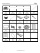
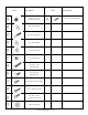
Parts & Hardware (for 60” diameter stair only) ① ② ③ ④ ⑤ Base Plate Bottom Baluster Main Balusters Center Balusters Single Threaded Column ⑥ ⑦ ⑧ ⑨ ⑩ Treaded Coupler Dual Threaded Column Tread Platform Column Ext with Cap (8.5” hub height) ⑪ ⑫ ⑬ ⑭ ⑮ Aluminum Handrail Top Baluster Bracket Aluminum HR End Cap Bottom Baluster Bracket Platform Rail ⑯ ⑰ ⑱ Extra Platform Rail Spacer (Optional) 5 Bottom Tread (5.75” hub height) www.mylenstairs.
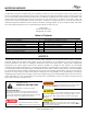
Item 6 Description Item Ⓐ 5/16”-18 x 5/16” Socket Set Screw Ⓑ 3/8” Flat Washer Ⓒ 3/8”x3” Lag Screw Ⓓ 1/4” Flat Washer Ⓔ 1/4” Lock Washer Ⓕ 1/4”-20 Hex Nut Ⓖ 1/4”-20 x 1-1/2” Carriage Bolt Ⓗ 1/4”-20 x 3/4” Carriage Bolt Ⓘ #10 x 3/4” SQ. Drive D&T Ⓡ #12-1” Baluster Screw Ⓢ 1/4”-20x1” Tube Connector Screw Ⓣ Tube Connector Ⓤ www.mylenstairs.
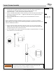
Center Column Assembly Hardware 1. Starting with a single threaded column section (5), screw a threaded coupler (6) into the threaded end of the column section until approximately 1” of the connector remains exposed. 2. Screw a double threaded column section (7) onto the exposed half of the threaded coupler from step 1. Tighten until there are no gaps between the column pieces. 3. Screw another threaded coupler (6) into the threaded end of the assembly.
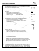
Platform and Base Installation Hardware 1. While all treads and platform are on the ground, partially thread set screws (A) into each tread and platform sleeve. 2. Partially thread set screws (A) into the baseplate (1). Insert the center column assembly into the baseplate until is fully seated. Attach the baseplate (1) to the center column assembly with set screws (A). 3. Determine the number of 1/8” spacers per rise using the following simple calculations: a.
you calculated in 3b. If you do not have wood tread covers, the measurement should be equal to the rise height calculated in 3b. 9. Place the number of spacers determined in 6b onto the center column assembly. 10. Place a tread (8) over the center column assembly. 11. Measure the rise from the top surface of the bottom tread to the top surface of the next tread. The measurement should be equal to the rise height calculated in 3b. 12. Repeat steps 9-11 for the remaining treads and platform.
Hardware 14. Plumb center column assembly and attach base plate to floor with 3/8”x3” lag bolts (C) and washers (B). Lead anchor shields (not supplied) will be needed if installing into concrete. ⒷⒸ Parts Tools The lag screws securing the base plate to the floor and the platform to the wall must be installed and fully tightened before continuing with the installation process. Failure to do so could cause the stair to be unstable and could result in serious injury or death. 15.
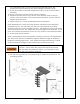
Tread and Baluster Installation Hardware 1. Start installation with the top tread. Place a main baluster (3) in the hole closest to the platform. Move the baluster up or down until the bottom of the baluster is flush with the bottom edge of the tread. 2. Attach this baluster to the tread using the carriage bolt (G), nut (F), washer (D) and lock washer (E). NOTE: Main Balusters have two holes drilled near the bottom. ⒹⒺⒻⒼ ⒽⒾ Parts ③ Tools 3.
5. Spin the next tread into position beneath the tread above. Place a main baluster through the upper tread and into the lower tread. Move up or down until the bottom of the baluster is flush with the bottom edge of the lower tread. 6. Secure the baluster to the lower tread using carriage bolt (G), nut (F), washer (D) and lock washer (E). 7. Fasten the baluster with carriage bolt (G), nut (F), washer (D) and lock washer (E). 8. Check that the tread is level and the baluster is plumb.
Bottom Baluster Installation Hardware NOTE: The main baluster connecting the bottom tread to the floor must be cut. 1. Cut approximately 1 ½” off the bottom of the last main baluster. 2. Place the bottom baluster bracket on the ground below the first tread. Guide the baluster through the hole in the first tread and into the hole of the bottom baluster bracket. 3. Adjust the height of the lower tread to be one riser height below the tread above.
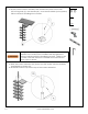
Aluminum Handrail Forming Hardware 1. The handrail is shipped in a coil that is typically between 36” and 48” in diameter. The first step to fitting the handrail is increasing this diameter to the proper coil diameter listed below. Stair Diameter Coil Diameter 3’-6” 60” 5’-0” 75” NOTE: The coil diameter should be larger than the stair diameter. 2. On a soft surface such as carpet, position the coil as depicted below. The cut end (1) should be approximately 4”-6” off the ground. 3.
7. Repeat steps 5 and 6 until the cut end is vertical. It should now be long enough to form by hand. 8. Hold the coil in place and pull the unsecured side outward and away from the center of the coil until the coil bends slightly. It may be necessary to brace the coil where it contacts the ground to prevent it from slipping while forming. 9. Continue rotating the coil and forming until the whole coil has been worked through. Measure the coil diameter to determine if more adjustment is needed.
Checking the Handrail Curvature Hardware 10. Lay the handrail down and find the cut end that contacts the ground. Use the method below to determine the orientation of the handrail. Parts ⑪ Tools NOTE: If the handrail orientation matches the orientation of the stairs being installed, skip to the next step. 11. Stand the handrail up. Push a cut end towards the center of the coil enough to clear the adjacent rail. Pull this cut end through the coil to the other side.
Pulling the Handrail into a Spiral Hardware 1. Determine the end to end length needed based on the diameter of the stair being installed. Stair Diameter End to End Length 3’-6” 14’ 5’-0” 11’ 2. With the help of another person, pull the handrail apart to the desired end to end length. Stop periodically to inspect the handrail for any kinks that may be forming. 17 www.mylenstairs.
Aluminum Handrail Installation Hardware 1. Once the Handrail has been shaped, dry fit the rail to the baluster tips. NOTE: The handrail may be slightly kinked on both ends. This is normal and the handrail should be positioned so that these ends can be cut off after installation. 2. Working together with another person, start at the top of the stair and install each screw (R) through the hole in the tip of each main baluster. Push or pull the handrail as needed to match it up with the baluster tip.
Center Baluster Installation Hardware 1. Measure each center baluster (4) from tip (at the handrail) to the top of the corresponding tread. NOTE: Do not cut all the balusters the same length. Measure each baluster position individually. Parts 2. Using a saw, cut each baluster to the correct length. ④ Tools 19 www.mylenstairs.
3. Insert bolt (S) through the tread and into hex nut (F). Do not fully tighten the hex nut. 4. Thread a tube connector (T) onto the exposed threads of the bolt until it is seated against the hex nut. Make sure the flanges on the tube connector are facing down towards the tread surface. Unscrew the tube connector one revolution to create a gap between the nut and the tube connector. 5. Ensure that the baluster tip is in line with the handrail, then slide the center baluster onto the tube connector. 6.
Platform Rail Installation 1. Place the platform rail onto the platform in the correct location. The platform rail will be approximately ¼” away from the column and ¼” away from the end of the platform. 2. Using the holes on the bottom of the platform rail as a template, mark the location of the holes on the top and side surface of the platform. 3. Drill a ¼” diameter hole in each location. 4. Using bolt (G), nut (F), washer (D) and split washer (E), secure the platform rail to the side of the platform. 5.