
Operating Instruction


EDGE FCR 3 Operating Instruction
Rev. C, 2019-09-10 Release Page 19 of 64
© MYNXG Product GmbH, 2019. All rights reserved
2.6 Interfaces on the MYNXG EDGE FCR 3
The MYNXG Edge FRC 3 contains on two sides connector and terminal bars, whose are:
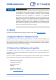
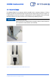
▪ EDGE FCR 3 POWER sidewall with the mandatory connectors (Figure 5):
o Power (24VDC),
o D-Sub (COM1),
o RJ45 for Gigabit Ethernet or ProfiNet (LAN1 / LAN2)
Figure 5: Side Wall 145, (UCS SW 145 F MYNXG POWER)
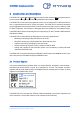
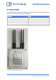
▪ EDGE FCR 3.1 DATA sidewall (Figure 6) which includes:
o Micro SIM card slot,
o USB 2.0 A connector,
o DisplayPort,
o Terminal block with 8 positions, push-in spring connection for HART or Current
Loop;
o Terminal block with 8 positions, push-in spring connection for Analog input (2x)
and external power supply to external sensors of 3.3V, 5V and 12V;
o Terminal block with 4 positions, push-in spring connection for I
2
C interface to
connect external Sensors with 3.3V external power supply
Figure 6:Side Wall 145, (UCS SW 145-F MYOMEGA DATA D31)