
Operating Instructions


SENSE MCE IBC Operating Instruction
Rev. D, 2020-12-15 Release Page 37 of 46
© MYNXG Product GmbH, 2020. All rights reserved
5.5 ISM Sub-1GHz Band
For the ISM Sub 1-GHz band signal generation and transmission, a low-power, high-
performance RF Transceiver from Texas Instruments (CC1200) is used. The transmitted and
the received signals are amplified with an RF Front End also from Texas Instruments, which
can be operated at 850 – 950 MHz (CC1190).
To get an increased ISM maximum output power of 23 dBm, a transmitted power level of -1.5
dBm is amplified with an analog front end in the output amplifier stage. With a gain of 24.5 dB
(High Gain Mode) and a noise figure of 2.9 dB the maximum power level is achieved in
consideration of the board losses (approximately 1.1 dB). This is the gain going out of the
Power Amplifier without calculating the peak gain of the printed antenna of peak gain of 0 dBi
(average gain of the printed antenna -6 dBi).
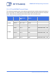
Table 9 shows the transmit power levels, receiver sensitivity and current consumption for each
used frequency at 915 MHz.
Table 9: RF specifications and current consumption
Parameter
Min
Typ.
Max
Unit
Conditions
Transmit Power
3
16
23
dBm
Receiver
Sensitivity
-
-115
-
dBm
100-kbps 2-GFSK, DEV=175 kHz,
CHF=514.423 kHz
9
Current
Consumption
-
220
-
mA
Output power of 23 dBm
Current
Consumption
-
160
-
mA
Output power of 16 dBm
9
GFSK is short for the frequency modulation Gaussian Frequency Shift Keying, DEV is short for deviation, CHF is short for
Channel Filter Bandwidth