ULTRAMETER ™ Operation Manual MODELS 6P & 4P 06 January 10
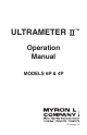
Instrument Illustration Reference Junction under Glass pH Bulb pH/ORP Sensor (Replaceable) ORP Electrode pH Glass Electrode Conductivity Cell (Built-in Electrodes) Temperature Sensor pH/ORP Sensor Protective Cap TEST Value Preprogrammed variable conductivity/ TDS ratios USER mode for programming special temperature compensation factor and conductivity/TDS ratio RATIO COND Time & Date displayed here ORP RES % / °C BUFFER pH TDS These Measurement keys will: • Turn instrument on • Measure parame
ii
I. INTRODUCTION Thank you for selecting the feature-packed Ultrameter II™, one of the Myron L Company’s latest in an increasing line of instruments utilizing advanced microprocessor-based circuitry and SMT manufacturing processes. This circuitry makes the instrument extremely accurate, reliable and very easy to use.
II. • • • • • • • • • • • • • • • FEATURES and SPECIFICATIONS A. Features Superior resolution 4 digit LCD displays full 9999 µS/ppm. Accuracy of BETTER than ±1% of reading in a handheld instrument. All electrodes are internal for maximum protection. Improved 4 electrode sensor technology. Waterproof to 1 meter/3 feet. Autoranging conductivity/TDS/resistivity. Prompts for easy pH calibration (6P). Factory calibrations stored in microprocessor.
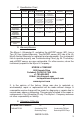
C. Specification Chart pH (6P) ORP (6P) Conductivity TDS Resistivity Temperature Ranges 0-14 pH ±999 mV 0-9999 µS/cm 10-200 mS/cm in 5 autoranges 0-9999 ppm 10-200 ppt in 5 autoranges 10KΩ - 30MΩ 0-71 °C 32 - 160 °F Resolution ±.01 pH ±1 mV 0.01 (<100 µS) 0.1 (<1000 µS) 1.0 (<10 mS) 0.01 (<100 mS) 0.1 (<200 mS) 0.01 (<100 ppm) 0.1 (<1000 ppm) 1.0 (<10 ppt) 0.01 (<100 ppt) 0.1 (<200 ppt) 0.01 (<100 KΩ) 0.1 (<1000 KΩ) 0.1 (>1 MΩ) 0.1 °C/F Accuracy ±.
TABLE OF CONTENTS Instrument Illustration . . . . . . . . . . . . . . . . . . . . . . . . . . . . . . . . . . . . . . . . . . . .i I. INTRODUCTION . . . . . . . . . . . . . . . . . . . . . . . . . . . . . . . . . . . . . . . . .1 II. FEATURES and SPECIFICATIONS. . . . . . . . . . . . . . . . . . . . . . . . .2 A. Features . . . . . . . . . . . . . . . . . . . . . . . . . . . . . . . . . . . . . 2 B. General Specifications . . . . . . . . . . . . . . . . . . . . . . . . . 2 C. Specification Chart .
C. Calibration Procedures . . . . . . . . . . . . . . . . . . . . . . . .15 1. Conductivity or TDS Calibration . . . . . . . . . .15 2. User Calibration Conductivity/TDS . . . . . . 15 3. Resistivity Calibration . . . . . . . . . . . . . . . . . . .16 4. Reloading Factory Calibration . . . . . . . . . . . .16 5. pH Calibration (6P) . . . . . . . . . . . . . . . . . . . . . 17 6. ORP Calibration (6P). . . . . . . . . . . . . . . . . . . .19 7. Temperature Calibration . . . . .
D. Soft Protective Carry Cases . . . . . . . . . . . . . . . . . 37 E. Hard Protective Carry Cases . . . . . . . . . . . . . . . . 37 F. Replacement pH/ORP Sensor (6P). . . . . . . . . . . . . . 37 G. uDock™ IR Data Port Accessory Package . . . . . . . 37 XX. TEMPERATURE COMPENSATION (Tempco) of Aqueous Solutions . . . . . . . . . . . . . . . . . . . . . . . . . . . . 37 A. Standardized to 25°C. . . . . . . . . . . . . . . . . . . . . . . . . . 37 B. Tempco Variation . . . . . . . . . .
III. RULES of OPERATION A. Operation Using the instrument is simple: • Individual or multiple parameter readings may be obtained by filling individual sensors or entire cell cup area. • Rinse the conductivity cell or pH/ORP sensor (6P) well with test solution 3 times and refill. Temperature and/or measurement extremes will require additional rinses for maximum accuracy. • Press the desired measurement key to start measurement. Pressing the key again restarts the 15 second auto “off” timer.
A press of b. RES Key displays resistivity with units on the right. On the left is shown solution type selected for resistivity (ref. Solution Selection, pg. 11). The range of display of resistivity is limited to between 10 kilohms (KΩ) and 30 megohms (MΩ). A solution outside that range will only show [- - - -] in the display. c. TDS Key A press of displays Total Dissolved Solids with units on the right.
5. UP or DOWN Keys While measuring in any parameter, the or keys activate the Memory Store and Memory Recall functions. While in CAL mode, the keys step or scroll the displayed value up or down. A single press steps the display and holding either key scrolls the value rapidly. While in Memory Recall, the keys scroll the display up and down through the stack of records (ref. Memory Recall, pg. 21). IV. AFTER USING the Ultrameter II A.
4. Take reading. A display of [- - - -] indicates an overrange condition. B. Measuring Resistivity Resistivity is for low conductivity solutions. In a cell cup the value may drift from trace contaminants or absorption from atmospheric gasses, so measuring a flowing sample is recommended. 1. Ensure pH protective cap is secure to avoid contamination. 2. Hold instrument at 30° angle (cup sloping downward). 3. Let sample flow continuously into conductivity cell with no aeration. 4.
3. Refill both sensor wells with sample. 4. Press 5. Take reading. 6. IMPORTANT: After use, fill pH/ORP sensor well with Myron L pH Sensor Storage Solution and replace protective cap. If Myron L pH Sensor Storage Solution is unavailable, use a strong KCl solution, a pH 4 buffer, or a saturated solution of table salt and tap water (ref. Cleaning Sensors, 2. pH/ORP, pg. 32). Do not allow pH/ORP sensor to dry out. . VI. SOLUTION SELECTION A.
you wish to change the solution type. 2. Press and hold KCl NaCl 442 User key for 3 seconds to make “SEL” appear (see Figure 1). For demonstration purposes, all 4 solution types are shown simultaneously. 3. Use the or Figure 1 key to select type of solution desired (ref. Solution Characteristics, pg. 40). The selected solution type will be displayed: KCl, NaCl, 442 or User. 4. Press to accept new solution type. E. Application of USER Solution Type 1.
2. Disabling Temperature Compensation a. Select USER mode, see Procedure to Select a Solution, pg. 11. b. With “USER” selected, press show .00%/°C, hold . If the display does not long enough to bring the tempco to .00%/°C (see Figure 3). c. Press twice (3 times if in TDS mode). Temperature compensation is now disabled (= 0) for measurements in USER mode. User % / °C COND Figure 3 3.
VII. CALIBRATION A. Calibration Intervals Generally, calibration is recommended about once per month with Conductivity or TDS solutions. Calibration with pH solutions should be checked twice a month. Calibration of ORP is not necessary (ref. CALIBRATION INTERVALS, pg. 19). B. Rules for Calibration of the Ultrameter II 1. Calibration Steps a. Starting Calibration Calibration is begun by pressing while measuring Conductivity, TDS or pH.
measurement key cancels changes not yet accepted and exits calibration mode. Leaving pH after the 2nd buffer results in the same gain being entered in place of the 3rd buffer. 2. Calibration Limits There are calibration limits. A nominal “FAC” value is an ideal value stored by the factory. Attempts to calibrate too far, up or down, from there will cause the displayed value to be replaced with “FAC”.
a. Rinse conductivity cell three times with your standard. b. Refill conductivity cell with same standard. c. Press or , then press twice in COND/three times in TDS. The “CAL” icon will appear on the display. d. Press or to step the displayed value toward the standard’s value or hold a key down to scroll rapidly through the reading. e. Press once to confirm new value and end the calibration sequence for this particular solution type. 3.
5. pH Calibration (6P) Important: Always “zero” your Ultrameter II with a pH 7 buffer solution before adjusting the gain with acid or base buffers, i.e., 4 and/or 10, etc. a. pH Zero Calibration (6P) 1. Rinse sensor well 3 times with 7 buffer solution. 2. Refill both sensor wells with 7 buffer solution. 3. Press to verify the pH calibration. If the display shows 7.00, skip the pH Zero Calibration and proceed to section b. pH Gain Calibration. 4.
reduce your variation from factory setting by pressing 6. Press or . to accept the new value. The pH Zero Calibration is now complete. You may continue with pH Gain Calibration or exit by pressing any measurement key. b. pH Gain Calibration (6P) Important: Always calibrate or verify your Ultrameter II with a pH 7 buffer solution before adjusting the gain with acid or base buffers, i.e., 4 and/or 10, etc.
6. Press to accept 2nd point of calibration. Now the display indicates the next type of buffer to be used. Single point Gain Calibration is complete. You may continue for the 3rd point of Calibration (2nd Gain) or exit by pressing any measurement key. Exiting causes the value accepted for the buffer to be used for both acid and base measurements. To continue with 3rd point calibration, use basic buffer if acidic buffer was used in the 2nd point, or vice-versa.
B. Calibration Tracking Records To minimize your calibration effort, keep records. If adjustments you are making are minimal for your application, you can check less often. Changes in conductivity calibration should be recorded in percent. Changes in pH calibration (6P) are best recorded in pH units. Calibration is purposely limited in the Ultrameter II to ±10% for the conductivity cell, as any change beyond that indicates damage, not drift.
IX. MEMORY This feature allows up to 100 readings with their temperatures to be stored simultaneously for later recall. At the same time, the TIME and DATE are also recorded. To download the memory to a computer, (ref. uDock™ IR Data Port, pg. 30). 1. 2. A. Memory Storage While displaying a measurement, press to record the displayed value.
1. Press and scroll to location #3. 2. Press and HOLD 3. Fill pH/ORP sensor well with sample. 4. Press to clear old record #3. to measure sample and press to store reading in location #3. 5. The next memory stored will go into location #8. 6. To clear all records: After pressing MEMORY , scroll down. “CLr ALL” will be displayed (see Figure 10). 7. Press . All records will Figure 10 be cleared. X. TIME and DATE The Time and Date may easily be changed as you travel. A.
4. Press the 5. Press or to change the time. to accept the change (new time). B. Setting DATE Example shown in Figure 12, is in US format i.e. mo/dy/yr. NOTE: The default format is US. Date format may be changed (ref. Date Format “US and International (Int)”, pg. 24). Figure 12 1. Press . 2. Press repeatedly until the date is displayed (stored readings, PC OFF, CLr ALL, time, date, i.e. 01.05/05 (January 5, 2005)). 3. Press to initiate.
8. Press the or CAL to change the day. 9. Press to accept the change (new day) (see Figure 15). Figure 15 C. DATE FORMAT “US & International (Int)” 1. Press . 2. Press repeatedly until the format is displayed (stored readings, PC OFF, CLr ALL, time, date, date format). 3. Press to change. Display will now indicate other format (see Figures 16 & 17). 4. Press any measurement key or allow to automatically turn off. Figure 16 Figure 17 XI. TEMPERATURE FORMAT “Centigrade & Fahrenheit” 1.
format location. The display will show a “C” or “F” (see Figures 18 and 19). Figure 18 Figure 19 4. Press to switch units. 5. Press to accept unit preference for all temperature readings. NOTE: Tempco will still be shown in %/°C. XII. TOTAL RETURN to FACTORY SETTINGS “FAC SEL” There may come a time when it would be desirable to quickly reset all the recorded calibration values in the instrument back to the factory settings.
XIII. CELL CHECK The cell check verifies the cleanliness of the conductivity/TDS/resistivity sensor. In normal use the cell may become dirty or coated and require cleaning. If the display is showing “.00” when the cell cup is dry, the sensor is probably clean. However, when testing high purity water in resistivity (RES) mode improved accuracy may be desired. No matter what a manufacturer claims, a sensor can and will become contaminated or coated; therefore require cleaning.
2. Press to display the stored memory records. 3. Press repeatedly until you pass the CELL ch location. The display will show “Auto oFF” (see Figure 24). 4. Press to initiate. CAL CAL will be displayed along with the “15 SEC” (see Figure 25). 5. Press or to change the time (see Figure 26). Maximum time is shown. 6. Press Figure 25 CAL to accept the change (new time). Figure 26 XV.
4. Verify/Set the calibration linc. (See below – Setting User Mode Calibration Linc). B. Setting User Mode Calibration “Linc” The Linc function sets or “links” the calibration gain factor of a Standard Solution to the User solution mode. Once set, the “Linc” will stay intact with future calibrations unless the Linc has been canceled. For more information on canceling the User Mode Calibration Linc refer to the section “Canceling User Mode Calibration Linc”, pg. 29.
6. Press key to accept the setting. Pressing any of the measurement keys will exit without changing the setting. User mode “Linc” is now complete. The User mode will now use the calibration gain constant used for the calibration of the Standard Solution as outlined above. C. Canceling User Mode Calibration “Linc” The Ultrameter II must be in User linked mode in order to cancel the “Linc”, (ref. SOLUTION SELECTION, pg. 11). 1. Press “Linked” measurement key , or .
to all measurement modes using User solution selection (i.e. TDS/User, Cond/User or Res/User). XVI. uDock™ IR DATA PORT INSTRUCTIONS Requires Myron L uDock™ accessory package, Model # U2CIP. The Myron L uDock is powered via the USB port, requiring no external power source. The uDock application will operate on Windows 2000 & XP*, and Macintosh OS9.2 & OSX** based computer systems. 1. A. Software Installation Place Myron L Ultrameter II uDock Installation CD into your computer. 2.
6. Press key. “PC On” will be displayed, (see Figure 31). The GREEN LED on the uDock will now be blinking periodically, indicating communication has been established between the Ultrameter II and the uDock. Figure 31 NOTE. “PC Ini” may momentarily be displayed while initializing, (see Figure 32). 7. On your computer, click on the data download button. A data transfer bar will appear while the data is being downloaded.
XVII. CARE and MAINTENANCE Ultrameter IIs should be rinsed with clean water after use. Solvents should be avoided. Shock damage from a fall may cause instrument failure. A. Temperature Extremes Solutions in excess of 71°C/160°F should not be placed in the cell cup area; this may cause damage. The pH sensor may fracture if the Ultrameter II temperature is allowed to go below 0°C/32°F. Care should be exercised not to exceed rated operating temperature.
allowed to dry out. However, if this occurs, the sensor may sometimes be rejuvenated by first cleaning the sensor well with Isopropyl alcohol or a liquid spray cleaner such as Windex™ or Fantastic™ and rinsing well. Do not scrub or wipe the pH/ORP sensor. Then use one of the following methods: 1. or 2.
XVIII. TROUBLESHOOTING CHART Symptom Possible Cause Inaccurate pH readings (6P) 1. pH calibration needed. Ref. pH Cal., pg. 17. 2. Cross-contamination from residual pH buffers or samples in sensor well. 3. Calibration with expired pH buffers. No display, even though measurement key pressed Battery weak or not connected. No response to pH changes Sensor bulb is cracked or an (6P) electromechanical short caused by an internal crack. Will not adjust down to pH 7 pH/ORP sensor has lost KCl.
Corrective Action Check connections or replace battery. Ref. Battery Replacement, pg. 32. 1. Recalibrate instrument. 2. Thoroughly rinse sensor well. 3. Recalibrate using fresh buffers. Ref. pH Buffer Solutions, pg. 36. Replace pH/ORP sensor. Ref. Replacement pH/ORP Sensor, pg. 37. Clean and rejuvenate sensor (ref. Cleaning Sensors, pg. 32) and recalibrate. If no improvement, replace pH/ORP sensor (ref. Replacement pH/ORP Sensor, pg. 37). Clean and rejuvenate sensor (ref. Cleaning Sensors, pg.
XIX. ACCESSORIES A. Conductivity/TDS Standard Solutions Your Ultrameter II has been factory calibrated with the appropriate Myron L Company NIST traceable KCl, NaCl, and our own 442™ standard solutions. Most Myron L conductivity standard solution bottles show three values referenced at 25°C: Conductivity in microsiemens/ micromhos, the ppm/TDS equivalents (based on our 442 Natural Water™) and NaCl standards. All standards are within ±1.0% of reference solutions. Available in 2 oz.
D. Soft Protective Carry Cases Padded Nylon carrying case features a belt clip for hands-free mobility. Two colors to choose from; Blue - Model #: UCC Desert Tan - Model #: UCCDT E. Hard Protective Carry Cases Large case with 2 oz. bottles of calibration standard solutions (KCl-7000, 442-3000, 4, 7, & 10 pH buffers and pH storage solution). Model #: PKUU Small case (no calibration standard solutions) - Model #: UPP F.
varies with concentration and temperature in a non-linear fashion. Other solutions have more variation still. The Ultrameter II uses corrections that change with concentration and temperature instead of single average values. See Chart 1. 2.500% 2.400% 2.300% 2.200% 2.100% % / °C 2.000% 1.900% 1.800% KCl % / °C 1.700% 1.600% 1.500% Temperature 0 5 10 15 20 25 30 Chart 1 35 40 45 50 55 60 C.
D. A Chart of Comparative Error In the range of 1000 µS, the error using KCl on a solution that should be compensated as NaCl or as 442, is illustrated in the graph below. 7% 442 error with KCl tempco 6% NaCl error with KCl tempco 5% 4% 3% 2% 1% 0% (1)% (2)% Temperature 0 5 10 15 20 25 30 35 40 45 50 55 Chart 2 Users wanting to measure natural water based solutions to 1% would have to alter the internal compensation to the more suitable preloaded “442” values or stay close to 25°C.
number to indicate a certain setpoint or minimum concentration or trend. The Ultrameter II gives the user the capability to collect data in “KCl conductivity units” to compare to older published data, in terms of NaCl or 442, or as appropriate. The Ultrameter II can be used to reconcile data taken with other compensation assumptions, especially with its ability to allow custom characteristics through the USER mode. XXI.
readings for a specific solution. That value remains a constant for all measurements, and should be reset for different dilutions or temperatures. C. When does it make a lot of difference? First, the accuracy of temperature compensation to 25°C determines the accuracy of any TDS conversion. Assume we have industrial process water to be pretreated by RO. Assume it is 45°C and reads 1500 µS uncompensated. 1.
over this change of 10°C. The solution is then said to have a tempco of 2.2 %/°C. Tempco always varies among solutions because it is dependent on their individual ionization activity, temperature and concentration. This is why the Ultrameter II features mathematically generated models for known salt characteristics that also vary with concentration and temperature. B.
XXIII. pH and ORP (6P) A. pH (6P) 1. pH as an Indicator (6P) pH is the measurement of Acidity or Alkalinity of an aqueous solution. It is also stated as the Hydrogen Ion activity of a solution. pH measures the effective, not the total, acidity of a solution. A 4% solution of acetic acid (pH 4, vinegar) can be quite palatable, but a 4% solution of sulfuric acid (pH 0) is a violent poison. pH provides the needed quantitative information by expressing the degree of activity of an acid or base.
The problem is, on the other side of the membrane is an unknown test solution, not potassium chloride. The outside electrode, also called the Reference Junction, is of the same construction with a porous plug in place of a glass barrier to Glass surface allow the junction fluid to contact Junction H+ ions the test solution without significant Plug migration of liquids through the plug material. Figure 33 shows a typical 2 component pair.
c. Temperature Compensation pH sensor glass changes its sensitivity slightly with temperature, so the further from pH 7 one is, the more effect will be seen. A pH of 11 at 40°C would be off by 0.2 units. The Ultrameter II senses the sensor well temperature and compensates the reading. B. ORP/Oxidation-Reduction Potential/REDOX (6P) 1. ORP as an Indicator (6P) ORP is the measurement of the ratio of oxidizing activity to reducing activity in a solution.
are much the same as for pH. The junction side is the same, and though the platinum surface will not break like the glass pH surface, its protective glass sleeve can be broken. A surface film will slow the response time and diminish sensitivity. It can be cleaned off with detergent or acid, as with the pH glass. XXIV. SOFTWARE VERSION Contact the Myron L Company to see if a software upgrade is available. 1. Press key. 2. Press key until three numbers are displayed as shown in Figure 35. 3.
XXV. GLOSSARY Anions Negatively charged ions. See Solution Characteristics, pg. 40. Algorithm A procedure for solving a mathematical problem. See Temperature Compensation and TDS Derivation, pg. 41. Logarithm An arithmetic function. See pH Units, pg. 43. ORP Oxidation-Reduction Potential or REDOX, See ORP/ Oxidation-Reduction Potential/REDOX, pg. 45. TDS Total Dissolved Solids or the Total Conductive Ions in a solution. See Conductivity Conversion to TDS, pg. 40.
XXVI.
XXVII.
Myron L COMPANY 2450 Impala Drive Carlsbad, CA 92010-7226 USA Tel: +1-760-438-2021 Fax: +1-760-931-9189 E-Mail: info@myronl.com techquestions@myronl.com www.myronl.