ULTRAMETER ™ Operation Manual MODELS 6Pfc & 4P 03 June 11
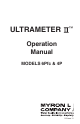
Instrument Illustration Reference Junction under Glass pH Bulb pH/ORP Sensor (Replaceable) ORP Electrode pH Glass Electrode Conductivity Cell (Built-in Electrodes) Temperature Sensor pH/ORP Sensor Protective Cap TEST Value Preprogrammed variable conductivity/ TDS ratios USER mode for programming special temperature compensation factor and conductivity/TDS ratio RATIO COND Time & Date displayed here ORP RES % / °C BUFFER pH TDS These Measurement keys will: • Turn instrument on • Measure parame
ii
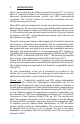
I. INTRODUCTION Thank you for selecting the feature-packed Ultrameter II™, one of the Myron L Company’s latest in an increasing line of instruments utilizing advanced microprocessor-based circuitry and SMT manufacturing processes. This circuitry makes the instrument extremely accurate, reliable and very easy to use. Model 6Pfc has been designed to include free chlorine measurements. Both Ultrameter IIs now also feature optional Bluetooth® wireless data transfer.
II. FEATURES and SPECIFICATIONS A. Features Bluetooth® wireless download capability with optional bluDock™ ORP mV to ppm free chlorine conversion (6Pfc) Superior resolution 4 digit LCD displays full 9999 µS/ppm Cond/TDS accuracy of ±1% of reading in a handheld instrument ±0.
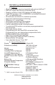
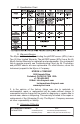
C. Specification Chart D. Warranty/Service The Myron L Ultrameter II, excluding the pH/ORP sensor (6Pfc), has a Two (2) Year Limited Warranty. The pH/ORP sensor (6Pfc) has a Six (6) Month Limited Warranty for materials and workmanship. If an instrument fails to operate properly, see Troubleshooting Chart, pg. 34. The battery and pH/ORP sensor are user-replaceable. For other service, return the instrument prepaid to the Myron L Company.
TABLE OF CONTENTS Instrument Illustration . . . . . . . . . . . . . . . . . . . . . . . . . . . . . . . . . . . . . . i I. INTRODUCTION . . . . . . . . . . . . . . . . . . . . . . . . . . . . . . . . . . . 1 II. FEATURES and SPECIFICATIONS . . . . . . . . . . . . . . . . . . . . . 2 A. Features . . . . . . . . . . . . . . . . . . . . . . . . . . . . . . . . . 2 B. General Specifications . . . . . . . . . . . . . . . . . . . . . . 2 C. Specification Chart . . . . . . . . . . . . . . . . . . . . . . . . .
TABLE OF CONTENTS B. Rules for Calibration of the Ultrameter II . . . . . . . 1. Calibration Steps . . . . . . . . . . . . . . . . . . . 2. Calibration Limits . . . . . . . . . . . . . . . . . . . C. Calibration Procedures . . . . . . . . . . . . . . . . . . . . . 1. Conductivity or TDS Calibration . . . . . . . 2. User Calibration Conductivity/TDS . . . . . 3. Resistivity Calibration . . . . . . . . . . . . . . . 4. Reloading Factory Calibration (Cond or TDS) . . . . . . . . . . . . . . . . . 5.
TABLE OF CONTENTS XVIII. TROUBLESHOOTING CHART . . . . . . . . . . . . . . . . . . . . . . . 34 XIX. ACCESSORIES . . . . . . . . . . . . . . . . . . . . . . . . . . . . . . . . . . . 36 A. Conductivity/TDS Standard Solutions . . . . . . . . . 36 B. pH Buffer Solutions (6Pfc) . . . . . . . . . . . . . . . . . . 36 C. pH Sensor Storage Solution (6Pfc) . . . . . . . . . . . 36 D. ORP Sensor Conditioner Solution (6Pfc) . . . . . . . 36 E. Soft Protective Carry Cases . . . . . . . . . . . . . . . . . 37 F.
III. RULES of OPERATION A. Operation Using the instrument is simple: • Individual or multiple parameter readings may be obtained by filling individual sensors or entire cell cup area. • Rinse the conductivity cell or pH/ORP sensor (6Pfc) well with test solution 3 times and refill. Temperature and/or measurement extremes will require additional rinses for maximum accuracy. • Press the desired measurement key to start measurement. Pressing the key again restarts the 15 second “Auto oFF” timer.
b. RES Key A press of displays resistivity with units on the right. On the left is shown solution type selected for resistivity (ref. Solution Selection, pg. 12). The range of display of resistivity is limited to between 10 kilohms (KΩ) and 30 megohms (MΩ). A solution outside that range will only show [- - - -] in the display. c. TDS Key A press of displays Total Dissolved Solids with units on the right.
5. UP or DOWN Keys While measuring in any parameter, the or keys activate the Memory Store and Memory Recall functions. While in CAL mode, the keys step or scroll the displayed value up or down. A single press steps the display and holding either key scrolls the value rapidly. While in Memory Recall, the keys scroll the display up and down through the stack of records (ref. Memory Recall, pg. 21). IV. AFTER USING the Ultrameter II A.
1. Ensure pH protective cap is secure to avoid contamination. 2. Hold instrument at 30° angle (cup sloping downward). 3. Let sample flow continuously into conductivity cell with no aeration. 4. Press key; use best reading. NOTE: If reading is lower than 10 kilohms display will be dashes: [ - - - - ]. Use Conductivity. 1. C. Measuring pH (6Pfc) Remove protective cap by rotating while grasping and pulling up. 2. Rinse pH/ORP sensor well and conductivity cell cup 3 times with sample to be measured.
3. Press the or keys to toggle between mV (standard ORP mode) and ppm (free chlorine measurement mode). The setting chosen is displayed. PPM 4. Press any parameter key to exit ORP unit preference selection or let the unit time out. ORP unit preference will be saved. 1. 2. Measuring ORP Ensure the 6Pfc is in ORP mode (ref. ORP Mode Selection, pg. 10). 2. Remove protective cap by rotating while grasping and pulling up. 3. Rinse sensor well and cell cup 3 times with sample to be measured.
2. Remove protective cap by rotating while grasping and pulling up. 3. Thoroughly flush the sensor well and cell cup with a steady stream of the solution you intend to measure by allowing the solution to flow into and out of the sensor well and cell cup for at least 10 seconds. 4. Refill both sensor well and cell cup with sample. 5. Press 6. Take reading. Annunciators alert you when the concentration is outside the specified measurement range.
D. Procedure to Select a Solution NOTE: Check display to see if solution displayed (KCl, NaCl, 442 or User) is already the type desired. If not: 1. Press , or to select the parameter on which you wish to change the solution type. 2. Press and hold key for 3 seconds to make “SEL” appear (see Figure 1). For demonstration purposes, all 4 solution types are shown simultaneously. 3. Use the or KCl NaCl 442 User Figure 1 key to select type of solution desired (ref. Solution Characteristics, pg. 40).
2. Disabling Temperature Compensation a. Select User mode (ref. Procedure to Select a Solution, pg. 13). b. With “User” selected, press . If the display does not show .00%/°C, hold long enough to bring the tempco to .00%/°C (see Figure 3). c. Press twice (3 times if in TDS mode). Temperature compensation is now disabled (=0) for measurements in User mode. User % / °C COND Figure 3 3.
VII. CALIBRATION A. Calibration Intervals Generally, calibration is recommended about once per month with Conductivity or TDS solutions. Calibration with pH solutions should be checked twice a month. Calibration of ORP is not necessary (ref. CALIBRATION INTERVALS, pg. 20). B. Rules for Calibration of the Ultrameter II 1. Calibration Steps a. Starting Calibration Calibration is begun by pressing while measuring Conductivity, TDS or pH.
2. Calibration Limits There are calibration limits. A nominal “FAC” value is an ideal value stored by the factory. Attempts to calibrate too far, up or down, from there will cause the displayed value to be replaced with “FAC”. If you accept it (press the “Cal” key), you will have the original default factory calibration for this measurement.
e. Press once to confirm new value and end the calibration sequence for this particular solution type. 3. Resistivity Calibration Resistivity is the reciprocal of Conductivity. To calibrate resistivity, calibrate conductivity for the solution type you wish to measure (ref. Conductivity or TDS Calibration, pg. 16). 4.
4. Press to enter calibration mode. The “CAL”, “BUFFER” and “7” annunciators will appear (see Figure 6, page 17). Displayed value will be the uncalibrated sensor. NOTES: If a wrong buffer is added (outside of 6-8 pH),“7” and “BUFFER” will flash, and the Ultrameter II will not adjust. The uncalibrated pH value displayed in step 4 will assist in determining the accuracy of the pH sensor.
CAL CAL BUFFER BUFFER Figure 7 pH Figure 8 pH NOTE: If the “Acd” and “bAS” indicators are blinking, the unit is indicating an error and needs either an acid or base solution present in the sensor well. 3. Rinse sensor well 3 times with acid or base buffer solution. 4. Refill sensor well again with same buffer solution. 5. Press or 6. Press to accept 2nd point of calibration. Now the until display agrees with buffer value. display indicates the next type of buffer to be used.
VIII. CALIBRATION INTERVALS There is no simple answer as to how often one should calibrate an instrument. The Ultrameter II is designed to not require frequent recalibration. The most common sources of error were eliminated in the design, and there are no mechanical adjustments. Still, to ensure specified accuracy, any instrument must be checked against chemical standards occasionally. A.
1. D. pH and ORP Practices to Maintain Calibration (6Pfc) Keep the sensor wet with Myron L Storage Solution. 2. Rinse away caustic solutions immediately after use. ORP calibration solutions are caustic, and ±5% is considered very accurate. By using the pH zero setting (0 mV = 7 pH) for ORP and precision electronics for detection, the Ultrameter II delivers better accuracy without calibration than a simpler instrument could using calibration solutions. IX.
C. Clearing a Record/Memory Clear After recalling a certain record location, press and HOLD to clear that memory. This space will be the place for the next memory record, unless you scroll to another empty position before ending the recall sequence. The next memory stored will go into the next highest available memory location. Example: You have locations 1-7 filled and wish to clear the conductivity reading stored in record location #3 and replace it with a pH reading. 1.
3. Press to initiate. “CAL” will be displayed along with the time (see Figure 11). 4. Press or to change the time. 5. Press to accept the change (new time). B. Setting DATE Example shown in Figure 12 is in US format, i.e., mo/dy/yr. NOTE: The default format is US. Date format may be changed (ref. Date Format “US and International (Int)”, pg. 24). Figure 12 1. Press . 2. Press repeatedly until the date is displayed (scrolling through stored readings, PC OFF, CLr ALL and time to the date, e.
8. Press or CAL to change the day. 9. Press to accept the change (new day) (see Figure 15). Figure 15 C. DATE FORMAT “US & International (Int)” 1. Press 2. Press . repeatedly until the format is displayed (scrolling through stored readings, PC OFF, CLr ALL, time and date to date format). 3. Press to change. Display will now indicate other format (see Figures 16 & 17). Figure 16 Figure 17 4. Press any measurement key or allow to automatically turn off. XI.
Figure 18 Figure 19 4. Press to switch units. 5. Press to accept unit preference for all temperature readings. NOTE: Tempco will still be shown in %/°C. XII. TOTAL RETURN to FACTORY SETTINGS “FAC SEL” There may come a time when it would be desirable to quickly reset all the recorded calibration values in the instrument back to the factory settings.
XIII. CELL CHECK The cell check verifies the cleanliness of the conductivity/TDS/resistivity sensor. In normal use the cell may become dirty or coated and require cleaning. If the display is showing “.00” when the cell cup is dry, the sensor is probably clean. However, when testing high purity water in resistivity (“RES”) mode improved accuracy may be desired. No matter what a manufacturer claims, a sensor can and will become contaminated or coated and, therefore, require cleaning.
2. Press to display the stored memory records. 3. Press repeatedly until you pass the CELL ch location. The display will show “Auto oFF” (see Figure 24, pg. 26). 4. Press to initiate. “CAL” CAL will be displayed along with “15 SEC” or current Auto oFF value (see Figure 25). 5. Press or to change the amount of time (see Figure 26). Maximum time is shown. 6. Press Figure 25 CAL to accept the change (new time). Figure 26 XV.
B. Setting User mode Calibration “Linc” The Linc function sets or “links” the calibration gain factor of a Standard Solution to the User solution mode. Once set, the “Linc” will stay intact with future calibrations unless the Linc has been canceled. For more information on canceling the User mode Calibration Linc refer to the section “Canceling User mode Calibration “Linc””, pg. 29. Follow the steps below to set either the KCl, NaCl or 442 calibration factor to the User solution mode. 1.
measurement keys will exit without changing the setting. User mode “Linc” is now complete. The User mode will now use the calibration gain constant used for the calibration of the Standard Solution as outlined above. C. Canceling User mode Calibration “Linc” The Ultrameter II must be in “User” linked mode in order to cancel the “Linc” (ref. SOLUTION SELECTION, pg. 12). 1. Press “Linked” measurement key , or . Two solution icons will be shown in the left side of display “User” and another, e.g., “KCl”.
XVI. bluDock™ Wireless Data Transfer INSTRUCTIONS NOTE: Bluetooth® is a registered trademark of Bluetooth SIG. The bluDock Bluetooth module is a registered Bluetooth device. Requires Myron L bluDock™ accessory package, Model # BLUDOCK. Package includes Ultrameter II hardware modification that allows the unit to communicate wirelessly with a personal computer configured for wireless device communication.
NOTE: “PC Ini” may momentarily be displayed while initializing (see Figure 32). 4. Add bluDock to your Bluetooth devices per your operating system procedure. The bluDock device Figure 32 passkey is 1234. 5. After pairing, note the number of the COM port assigned by the computer. In Windows XP, note the number of the outgoing COM port assigned by the computer. NOTE: The unit will automatically power down after 60 sec. If the unit powers down during pairing, repeat steps 1-3 above and continue. 1. 2. 3. C.
XVII. CARE and MAINTENANCE Ultrameter IIs should be rinsed with clean water after use. Solvents should be avoided. Shock damage from a fall may cause instrument failure. A. Temperature Extremes Solutions in excess of 71°C/160°F should not be placed in the cell cup area; this may cause damage. The pH sensor may fracture if the Ultrameter II temperature is allowed to go below 0°C/32°F. Care should be exercised not to exceed rated operating temperature.
beallowed to dry out. However, if this occurs, the sensor may sometimes be rejuvenated by first cleaning the sensor well with Isopropyl alcohol or a liquid spray cleaner such as Windex™ or Fantastic™ and rinsing well. Do not scrub or wipe the pH/ORP sensor. Then use one of the following methods: 1. or 2.
XVIII. TROUBLESHOOTING CHART Symptom Possible Cause No display, even though measurement key pressed Battery weak or not connected. Inaccurate pH readings (6Pfc) 1. pH calibration needed. Ref. pH Cal., pg. 17. 2. Cross-contamination from residual pH buffers or samples in sensor well. 3. Calibration with expired pH buffers. No response to pH changes (6Pfc) Sensor bulb is cracked or an electromechanical short caused by an internal crack.
Corrective Action Check connections or replace battery. Ref. Battery Replacement, pg. 32. 1. Recalibrate instrument. 2. Thoroughly rinse sensor well. 3. Recalibrate using fresh buffers. Ref. pH Buffer Solutions, pg. 36. Replace pH/ORP sensor. Ref. Replacement pH/ORP Sensor, pg. 37. Clean and rejuvenate sensor (ref. Cleaning Sensors, pg. 32) and recalibrate. If no improvement, replace pH/ORP sensor (ref. Replacement pH/ORP Sensor, pg. 37). Clean and rejuvenate sensor (ref. Cleaning Sensors, pg.
XIX. ACCESSORIES NOTE: MSDSs are available on the Myron L website for all solutions: http://www.myronl.com/main/Material_Safety_DS_DL.htm A. Conductivity/TDS Standard Solutions Your Ultrameter II has been factory calibrated with the appropriate Myron L Company NIST traceable KCl, NaCl, and our own 442™ standard solutions.
E. Soft Protective Carry Cases Padded Nylon carrying case features a belt clip for hands-free mobility. Two colors to choose from: Blue - Model #: UCC Desert Tan - Model #: UCCDT F. Hard Protective Carry Cases Large case with 2 oz. bottles of calibration standard solutions (KCl-7000, 442-3000, 4, 7, & 10 pH buffers and pH storage solution). Model #: PKUU Small case (no calibration standard solutions) - Model #: UPP G.
2.500% 2.400% 2.300% 2.200% 2.100% % / °C 2.000% 1.900% 1.800% KCl % / °C 1.700% 1.600% 1.500% Temperature 0 5 10 15 20 25 30 Chart 1 35 40 45 50 55 60 C. An Example of 2 different solution selections and the resulting compensation How much error results from treating natural water as if it were KCl at 15°C? A tap water solution should be compensated as 442 with a tempco of 1.68 %/°C, where the KCl value used would be 1.90 %/°C.
7% 442 error with KCl tempco 6% NaCl error with KCl tempco 5% 4% 3% 2% 1% 0% (1)% (2)% Temperature 0 5 10 15 20 25 30 35 40 45 50 55 Chart 2 E. Other Solutions A salt solution like sea water or liquid fertilizer acts like NaCl. An internal correction for NaCl can be selected for greatest accuracy with such solutions. Many solutions are not at all similar to KCl, NaCl or 442.
A. How it’s Done Once the effect of temperature is removed, the compensated conductivity is a function of the concentration (TDS). Temperature compensation of the conductivity of a solution is performed automatically by the internal processor with data derived from chemical tables. Any dissolved salt at a known temperature has a known ratio of conductivity to concentration. Tables of conversion ratios referenced to 25°C have been published by chemists for decades. B.
If none of the 3 standard solutions apply, the User mode must be used. Temperature Compensation (Tempco) and TDS Derivation below, details the User mode. XXII. TEMPERATURE COMPENSATION (Tempco) and TDS DERIVATION The Ultrameter II contains internal algorithms for characteristics of the 3 most commonly referenced compounds. The solution type in use is displayed on the left. Besides KCl, NaCl, and 442, there is the User choice.
There is a ratio of TDS to compensated conductivity for any solution, which varies with concentration. The ratio is set during calibration in User mode as in User Programmable Conductivity to TDS Ratio, pg. 14. A truly unknown solution has to have its TDS determined by evaporation and weighing. Then the solution whose TDS is now known can be measured for conductivity and the ratio calculated. Next time the same solution is to be measured, the ratio is known. XXIII. pH and ORP (6Pfc) A. pH (6Pfc) 1.
still produce an offset voltage, but using the same materials to connect to the solution on the other side of the membrane causes the 2 equal offsets to cancel. The problem is, on the other side of the membrane is an unknown test solution, not potassium chloride.
c. Temperature Compensation pH sensor glass changes its sensitivity slightly with temperature, so the further from pH 7 one is, the more effect will be seen. A pH of 11 at 40°C would be off by 0.2 units. The Ultrameter II 6Pfc senses the sensor well temperature and compensates the reading. B. ORP/Oxidation-Reduction Potential/REDOX (6Pfc) 1. ORP as an Indicator (6Pfc) ORP is the measurement of the ratio of oxidizing activity to reducing activity in a solution.
C. Free Chlorine 1. Free Chlorine as an Indicator Chlorine is a germicide used in the disinfection of drinking water, wastewater, and recreational waters. It is dissolved in water and reacts with water to form the hypochlorite ion and hypochlorous acid, the concentrations of which are directly dependent on pH. Some chlorine is initially consumed by organic matter and metal ions present in solution. The amount of chlorine a particular solution consumes is called chlorine demand.
XXV. GLOSSARY Anions Negatively charged ions. See Solution Characteristics, pg. 40. Algorithm A procedure for solving a mathematical problem. See Temperature Compensation (Tempco) and TDS Derivation, pg. 41. Free Chlorine The amount of chlorine that remains active in solution and is available for ongoing disinfection. See Free Chlorine as an Indicator, pg. 45. Logarithm An arithmetic function. See pH Units, pg. 42.
High Performance Features: • Accuracy of ±1% of READING ±.
Myron L COMPANY 2450 Impala Drive Carlsbad, CA 92010-7226 USA Tel: +1-760-438-2021 Fax: +1-760-931-9189 E-Mail: info@myronl.com techquestions@myronl.com www.myronl.