
Instruction Manual


4. Turn the front panel around so that the back side is
facing you and set aside for now.
5. Carefully remove front panel, leaving the harness
connected.
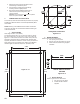
6. Using the enclosure cutouts, install the proper wire and
watertight cable restraint (not provided) to comply with
local electrical codes.
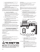
7. Neatly connect wires to the Main Circuit Board
connectors,asshowningureII.E.1.
*CAUTION: The input power connectors require only a small
screwdriver or a pen to push on the release levers. The release
levers may be broken or damaged if not pushed straight toward
the circuit board. DO NOT push the release levers sideways.
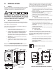
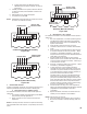
2. 115/230 VAC CONVERSION
1. Before turning power on to the Monitor/controller
ensure the proper input voltage has been selected.
Failure to do so will blow the fuse. It could, under some
conditions, cause injury and damage the instrument
voiding the warranty.
2. Locate switch located next to the fuse holder.
3. Using a screwdriver, turn switch to required voltage.
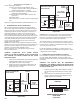
3. CONNECTING THE SENSOR CABLE
For OEM models skip #1.
1. Place the Sensor’s interface cable and user supplied
watertight cable restraint into the enclosure’s
appropriate access hole.
2. Install the sensor cable wire to comply with local
electrical codes. Follow the color code as marked.
SeegureII.E.1.
*CAUTION: The sensor connectors require only a small
screwdriver or a pen to push on the release levers. The release
levers may be broken or damaged if not pushed straight toward
the circuit board. DO NOT push the release levers sideways.
a. MODIFICATION FOR US PHARMACEUTICAL
25 (No Temperature Compensation)
ThissimplemodicationwillallowyourMonitor/controller
to meet the USP 25 requirements by defeating the normal
temperature compensation circuit thus giving “uncompensated”
readings as required.
Specications:
As required to meet USP25.
Installation
Briey-
For Conductivity/TDS, a resistor is installed in place of the
sensor “temperature” sensing leads.
For Resistivity, two resistors are installed in place of the sensor
“temperature” sensing leads.
The extra sensor leads are either cut off or the ends are
wrapped in tape to prevent shorting.
WARNING: BEFORE STARTING, IF MONITOR/
CONTROLLER IS INSTALLED, ENSURE THE POWER IS
OFF. FAILURE TO DO SO COULD CAUSE DAMAGE TO
THE INSTRUMENT, AND COULD BE HARMFUL OR FATAL
TO PERSONNEL. ONLY QUALIFIED PERSONNEL SHOULD
INSTALL OR SERVICE ELECTRICAL EQUIPMENT.
Requirements:
ForConductivity/TDS;one10kΩ1%resistor,usersuppliedor
may be ordered from the Myron L Company.
ForResistivity;one100kΩ1%resistor,andone5.49kΩ
1% resistor, user supplied or may be ordered from the
Myron L Company.
NOTE: When opening instrument, remove front cover with care;
a ribbon cable connects the front panel and main board. If the
front panel has all ready been removed from the enclosure skip
to #4.
1. Using a standard slot screwdriver remove the four (4)
screws on the front panel.
2. Carefully wiggle the front panel to loosen and pull
gently toward you. Do not pull more than about 8
inches/20CM or you could damage the wiring harness.
3. Turn the front panel around so that the back side is
facing you and set aside.
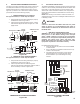
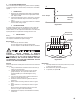
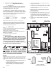
4. For Conductivity/TDS Monitor/controllers;
a. If sensor is installed, locate and remove the RED
(RD) and the GREEN (GN) leads from MAIN
CircuitBoard,asshowningureII.E.2.
b. Cut off or tape RED (RD) and the GREEN (GN)
leads from sensor.
c. Install10kΩresistoratRED(RD)andtheGREEN
(GN)connectorlocations,asshowningure
II.E.3.
For Resistivity Monitor/controllers;
a. If sensor is installed, locate and remove the
GREEN (GN), RED (RD), and the NEUTRAL (NU)
leadsfromMAINCircuitBoard,asshowningure
II.E.4.
b. Cut off or tape GREEN (GN), RED (RD), and the
NEUTRAL (NU) leads from sensor.
c. Install100kΩresistoratBLACK(BK)andGREEN
(GN)connectorlocations,asshowningure
II.E.5.
12
Conductivity/TDS Main CB Assembly
Figure II.E.2
-121
2000µS
UP
}
HYS1SP1FS SW
BK WT RD GN NU R- R+
DIS
CAL
3S
FULL SCALE
PUSH TO TEST
INC
DEC
SPC
0-10VDC
OUTPUT
SENSOR LEADS
REMOVE THESE TWO LEADS
!
CAUTION - READ FOLLOWING CAREFULLY