Ultrameter III™ Operation Manual MODEL 9PTK 17 June 2013
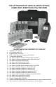
The 9P titration kit (with bludock option) Comes with Everything You See Here 3 6 7 12 13 14 8 15 4 9 10 11 16 17 1 19 18 5 2 22 1. 2. 3. 4. 5. 6. 7. 8. 9. 10. 11. 12. 13. 14. 15. 16. 17. 18. 19. 20. 21. 22. 20 21 PLEASE CHECK THE CONTENTS OF YOUR KIT! Ultrameter III™ Model 9P Cell Extender Model TKCE Foam-lined hard carry case M’PET 100µL fixed volume pipette Model FVMP-100 12 disposable pipette tips 2oz. bottle of Alkalinity Standard Solution Model ALK-1002OZ 2oz.
ii
I. INTRODUCTION Thank you for selecting the feature-packed Ultrameter III™, one of the Myron L Company’s latest in an increasing line of instruments utilizing advanced microprocessor-based circuitry and SMT manufacturing processes. This circuitry makes the instrument extremely accurate, reliable and very easy to use. The Ultrameter III™ has been designed to include titration measurements for Alkalinity, Hardness and LSI and an LSI Calculator for water balance analysis.
II. FEATURES and SPECIFICATIONS • • • • • • • • • • • • • • • • • • A. Features ORP-based FCE Free Chlorine measurement; displays as ppm concentration Alkalinity and Hardness Conductometric Titrations Langelier Saturation Index (LSI) Titrations and Calculator Superior resolution 4 digit LCD displays full 9999 µS/ppm Cond/TDS Accuracy of ±1% of reading / ±0.
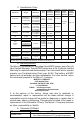
C. Specification Chart Parameters Ranges Conductivity 0-9999µS/cm 10-200mS/cm in 5 autoranges TDS 0-9999ppm 10-200ppt in 5 autoranges Resistivity 10KΩ-30MΩ Resolution 0.01(<100µS) 0.1(<1000µS) 1.0(<10mS) 0.01(<100mS) 0.1(<200mS) 0.01(<100ppm) 0.1(<1000ppm) 1.0(<10ppt) 0.01(<100ppt) 0.1(<200ppt) 0.01(<100KΩ) 0.1(<1000KΩ) 0.1(>1MΩ) Accuracy Auto Temperature Compensation ±1% of reading 0-71ºC 32-160ºF ±1% of reading 0-71ºC 32-160ºF 0-9.99%/ºC ±1% of reading 0-71ºC 32-160ºF 0-9.
PLEASE NOTE: Because of our commitment to product improvement, the substance and style of this manual may change. When changes are made, the updated manual is posted for download in PDF format from the Myron L Website: www.myronl.
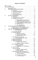
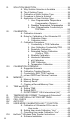
TABLE OF CONTENTS 9PTK Contents . . . . . . . . . . . . . . . . . . . . . . . . . . . . . . . . . . . . . . . . . . . i Instrument Illustration . . . . . . . . . . . . . . . . . . . . . . . . . . . . . . . . . . . . . . ii I. INTRODUCTION . . . . . . . . . . . . . . . . . . . . . . . . . . . . . . . . . . . 1 II. FEATURES and SPECIFICATIONS . . . . . . . . . . . . . . . . . . . . . 2 A. Features . . . . . . . . . . . . . . . . . . . . . . . . . . . . . . . . . 2 B. General Specifications . . . . . . . .
VI. VII. VIII. IX. X. XI. XII. XIII. XIV. XV. XVI. 6 SOLUTION SELECTION . . . . . . . . . . . . . . . . . . . . . . . . . . . . A. Why Solution Selection is Available . . . . . . . . . . . B. The 4 Solution Types . . . . . . . . . . . . . . . . . . . . . . C. Calibration of Each Solution Type . . . . . . . . . . . . D. Procedure to Select a Solution . . . . . . . . . . . . . . . E. Application of User Solution Type . . . . . . . . . . . . 1. User Programmable Temperature Compensation (Tempco) . . .
B. Hardware Setup . . . . . . . . . . . . . . . . . . . . . . . . . . C. Memory Stack Download . . . . . . . . . . . . . . . . . . . XVII. CARE and MAINTENANCE . . . . . . . . . . . . . . . . . . . . . . . . . . A. Temperature Extremes . . . . . . . . . . . . . . . . . . . . . B. Battery Replacement . . . . . . . . . . . . . . . . . . . . . . C. pH/ORP Sensor Replacement . . . . . . . . . . . . . . . D. Cleaning Sensors . . . . . . . . . . . . . . . . . . . . . . . . . XVIII. TROUBLESHOOTING . . . . . . . .
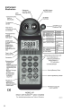
III. RULES of OPERATION A. Operation NOTE: The cell extender does not interfere with normal operation. Using the instrument is simple: • • • • • • • • • • Individual or multiple parameter readings may be obtained by filling individual sensors or entire cell cup area. Rinse the conductivity cell and/or pH/ORP sensor well with test solution 3 times and refill. Temperature and/or measurement extremes will require additional rinses for maximum accuracy.
2. COND, RES and TDS Keys These 3 keys are used with solution in the Conductivity Cell. Precautions: • While filling cell cup, ensure no air bubbles cling on the cell wall. • If the proper solution is not selected (KCl, NaCl, 442 or User), refer to Why Solution Selection is Available, pg. 24 and Procedure to Select a Solution, pg. 25. a. COND Key Solution to be tested is introduced into the conductivity cell and a press of displays conductivity with units on the right.
4. pH and ORP/Fr Chl Keys Measurements are made on solution held in the pH/ORP sensor well (ref. pH and ORP/Free Chlorine, pg. 64). The protective cap is removed and the sensor well is filled and rinsed with the sample enough times to completely replace the storage solution. After use, the pH/ORP sensor well must be refilled with Myron L Storage Solution, and the protective cap reinstalled securely (ref. Maintenance of the pH/ORP Sensor, pg. 11 and Cleaning Sensors, 2. pH/ORP, pg. 52). a.
the display and holding either key scrolls the value rapidly. While in calibration or calculator mode, the keys step or scroll the displayed value up or down. While in Memory Recall, the keys scroll the display up and down through the stack of records (ref. Memory Recall, pg. 39). IV. AFTER USING the Ultrameter III A. Maintenance of the Conductivity Cell Rinse out the cell cup with clean water. Do not scrub the cell. For oily films, squirt in a foaming non-abrasive cleaner and rinse (ref.
1. Pipette Instructions Always use a clean tip when changing solutions! To install a tip, press the wide end of the tip on the end of the pipette until it is secure. To remove a tip, simply pull it off the end of the Shaft Coupling pipette. Plunger Button CE Plunger Rod 100µl 100 µL NOTE: The accuracy of titration measurements is affected by your technique. Be careful when removing the cap of the cell extender to add reagents.
conductivity cell being careful not to touch the tip to the existing solution. Depress the top of the pipette to the SECOND STOP (all the way down) being careful to keep the tip over the cell. Release the plunger button and let it return to the REST position. 2. T-Plunger Instructions To PLUNGE the cell: With the cell extender installed and solution in the cell, insert the tip of the T-plunger in the cell extender until the arms of the T-plunger are flush against the rim of the cell extender.
Agitate and hold as many times as prompted. Allow the display to cycle through all screens, e.g., “EdTA”, “AGit” and “HOLd”, at least once. Continue holding steady until “PrES CAL” displays. Hold the unit steady before pressing CAL to accept readings. 1. “HOLd”: When “HOLd” displays, hold the 9P still with bottom of case parallel to the ground. C. Measuring Conductivity & Total Dissolved Solids (TDS) Rinse cell cup 3 times with sample to be measured.
3. Rinse the conductivity cell cup and cell extender 3 times with solution to be measured. 4. Refill cell cup and cell extender with sample solution. 5. Insert T-plunger into open cell extender until the “T” rests flush on the lip of the cell extender. This will cause fluid beyond what is required for titration to overflow the cell extender. 6. Rotate the T-plunger from side to side, allowing the arms of the T-plunger to slide along the rim of the cell extender. 7.
14. unit as prompted, then pressing CAL as prompted. An alkalinity value will display when the titration measurement is complete. Note the value for your records or press MS to store the value. You can begin another Alkalinity titration by pressing ALK. The unit will automatically power off after the period of inactivity defined in the AUTO OFF setting (ref. AUTO OFF, pg. 45). F. Measuring Hardness 1.
7. Carefully remove the T-plunger so as not to flick or spill remaining sample. Tap the T-plunger on the side of the cell extender to remove sample that may be stuck to the T-plunger. 8. Press 9. 10. 11. . “CA” alternating with “tdS” displays along with “PPM” sample value. “PrES CAL” displays when the reading stabilizes. Press CAL. “Add” alternating with “C1” will display; then “AGit” alternating with “HOLd” will display.
18. 19. 20. 21. 22. 23. 24. cell, close the cell extender cap securely to prevent any solution from spilling out, then agitate and hold. Repeat as prompted. “PrES CAL” will display. Press CAL to advance to first titration prompt. “Add” alternating with either “EdTA LC” (Reagent H2) or “EdTA HC” (Reagent H3) will display; then “AGit t1” alternating with “HOLd” will display. The number after “t” indicates which titration point you are on. The number “1” here indicates this is the first titration point.
All other values will display as default. You can adjust any or all of the values displayed to determine the effect of the change(s) on the LSI value. 1. Measuring LSI NOTE: The unit will automatically power off after the period of inactivity defined in the AUTO OFF setting (ref. AUTO OFF, pg. 45).
To compute saturation index using hypothetical alkalinity, hardness, pH or temperature values: 1. Press . 2. Either the last stored value or the default value of “120” is displayed. 3. Press the UP or DOWN keys to adjust the alkalinity value or leave as displayed. 4. Press CAL to accept and advance to the hardness value screen. Either the last stored value or the default value of “166” is displayed. 5. Press CAL to accept hardness value and advance to the pH value screen.
of table salt and tap water (ref. Cleaning Sensors, 2. pH/ORP, pg. 52). Do not allow pH/ORP sensor to dry out. I. Measuring ORP The Ultrameter III features the ability to measure the activity of oxidizing or reducing chemicals in solution as ORP mV. The instrument also includes an innovative Free Chlorine Equivalent (FCE) feature (Measuring Free Chlorine Using FCE, pg. 22) that uses ORP and pH to measure free available chlorine (FAC) concentration in ppm.
1. 2. Measuring ORP Ensure the 9P is in ORP mode (ref. ORP/FCE Mode Selection, pg. 21). 2. Remove protective cap by rotating while grasping and pulling up. 3. 4. Rinse sensor well and cell cup 3 times with sample to be measured. Shake out each sample to remove any residual liquid. Refill both sensor well and cell cup with sample. 5. Press 6. Take reading. 7. Press MS to store reading in memory, if desired. .
solution to flow into and out of the sensor well and cell cup for at least 10 seconds. 4. Let sample flow continuously into conductivity cell with no aeration. 5. Allow both the sensor well and cell cup to remain filled with sample. 6. Press . The instrument will begin alternating between a predicted final ORP value and a free chlorine equivalent concentration in ppm. Both readings will change rapidly at first. 7. Wait for the readings to stabilize.
NOTE: If the reading takes longer than 1 minute to stabilize, press after 1 minute to prevent Auto-OFF feature from disturbing the measurement process. Annunciators will alert you when either the pH or ORP of the final FCE ppm value are Out of Range (“-Or-”). 7. Press MS to store reading in memory if desired. 4. FCE Best Practices For best results it is recommended that you: 1. Take 3 consecutive FCE measurements and record the readings. 2. Calculate the average of the 3 measurements. Use this value.
pg. 29) is performed separately for each type of solution one wishes to measure (ref. Conductivity/TDS Standard Solutions, pg. 56). D. Procedure to Select a Solution NOTE: Check display to see if solution displayed (KCl, NaCl, 442 or User) is already the type desired. If not: 1. Press , or to select the parameter on which you wish to change the solution type. 2. Press and hold key for 3 seconds to make “SEL” appear (see Figure 1).
c. Press twice to skip calibration adjustment and accept the new tempco (3 times if in TDS mode). You are now ready to measure samples with your new temperature compensation factor. 2. Disabling Temperature Compensation a. Select User mode (ref. Procedure to Select a Solution, pg. 25). b. With “User” selected, press show .00%/°C, hold . If the display does not long enough to bring the tempco to .00%/°C (see Figure 3). c. Press twice (3 times if in TDS mode).
a. While in User mode, press b. Press . twice (to skip over tempco adjustment) and “RATIO” will appear (see Figure 4). c. Adjust with displayed. d. Press or key until new conversion ratio is twice (to skip over calibration adjustment) to accept new conversion ratio. You are now ready to measure samples with the new conductivity/TDS ratio. VII. CALIBRATION A. Calibration Intervals Generally, calibration is recommended about once per month with Conductivity or TDS solutions.
calibration intervals table: Function KCl, NaCl or 442 Cond Gain Only Res Done in Conductivity TDS Gain Only pH 7, acid and/or base ORP Zero set with pH 7 automatically Alkalinity Gain Only Hardness Gain Only User Tempco, then Gain Done in Conductivity Tempco, Ratio, then Gain a. Starting Calibration For Alkalinity and Hardness, calibration is begun by pressing when the titration is complete and a value displays.
calibrate beyond its calibration limits. For all other functions, attempts to calibrate too far up or down from the ideal “FAC” value stored in the unit by the factory will cause the displayed value to be replaced with “FAC”. If you accept it (press the CAL key), you will have the original default factory calibration for this measurement. The need to calibrate so far out that “FAC” appears indicates a procedural problem, incorrect standard solution, a very dirty cell cup or an aging pH/ORP sensor (ref.
d. Press or to step the displayed value toward the standard’s value or hold a key down to scroll rapidly through the reading. e. Press once to confirm new value and end the calibration sequence for this particular solution type. 3. Resistivity Calibration Resistivity is the reciprocal of Conductivity. To calibrate resistivity, calibrate conductivity for the solution type you wish to measure (ref. Conductivity or TDS Calibration, pg. 29). 4.
1. Ensure pH protective cap is secure to avoid contamination. 2. Install the cell extender by pushing the base of the cell extender into the conductivity cell until it is fully seated. 3. Rinse the conductivity cell cup and cell extender 3 times with Alkalinity Standard 100PPM. 4. Refill cell cup and cell extender with Alkalinity Standard 100PPM. 5. Insert T-plunger into open cell extender until the “T” rests flush on the lip of the cell extender.
12. Tap the cell extender cap to dispel any solution clinging to the cap back into the cell. Carefully open the cell extender cap so as not to spill any solution. 13. Continue adding 100µL of Reagent A1, agitating and holding the unit as prompted, then pressing CAL as prompted. An alkalinity value will display when the titration measurement is complete. 14. Press CAL. The “CAL” icon will display. 15. Adjust the displayed value to “100” using the UP or DOWN key.
6. Rotate the T-plunger from side to side, allowing the arms of the T-plunger to slide along the rim of the cell extender. 7. Carefully remove the T-plunger so as not to flick or spill remaining sample. Tap the T-plunger on the side of the cell extender to remove sample that may be stuck to the T-plunger. 8. Press . “CA” alternating with “tdS” displays along with “PPM” sample value. “PrES CAL” displays when the reading stabilizes. 9. Press CAL.
17. Using the pipette, add a second 100 µL of Reagent H1 to the cell, close the cell extender cap securely to prevent any solution from spilling out, then agitate and hold. Repeat as prompted. “PrES CAL” will display. 18. Press CAL to advance to first titration prompt. “Add” alternating with either “EdTA LC” (Reagent H2) or “EdTA HC” (Reagent H3) will display; then “AGit t1” alternating with “HOLd” will display. The number after “t” indicates which titration point you are on.
solution before adjusting the gain with acid or base buffers, i.e., 4 and/ or 10, etc. a. pH Zero Calibration 1. Rinse sensor well and cell cup 3 times with 7 buffer solution. 2. Refill both sensor well and cell cup with 7 buffer solution. 3. Press to verify the pH calibration. If the display shows 7.00, skip the pH Zero Calibration and proceed to section b. pH Gain Calibration. 4. Press to enter calibration mode. The “CAL”, “BUFFER” and “7” annunciators will appear (see Figure 6).
is now complete. You may continue with pH Gain Calibration or exit by pressing any measurement key. b. pH Gain Calibration Important: Always calibrate or verify your Ultrameter III with a pH 7 buffer solution before adjusting the gain with acid or base buffers, i.e., 4 and/or 10, etc. Either acid or base solution can be used for the 2nd point “Gain” calibration and then the opposite for the 3rd point. The display will verify that a buffer is in the sensor well by displaying either “Acd” or “bAS”. 1.
To continue with 3rd point calibration, use basic buffer if acidic buffer was used in the 2nd point, or vice-versa. Again, match the display to the known buffer value as in step 2 and continue with the following steps: 7. Repeat steps 3 through 6 using opposite buffer solution. 8. Press to accept 3rd point of calibration, which completes the Calibration procedure. Fill sensor well with Myron L Storage Solution and replace protective cap. 8.
C. Conductivity, RES, TDS, Practices to Maintain Calibration 1. Clean oily films or organic material from the cell electrodes with foaming cleaner or mild acid. Do not scrub inside the cell. 2. Calibrate with solutions close to the measurements you make. Readings are compensated for temperature based on the type of solution. If you choose to measure tap water with a KCl compensation, which is often done (ref. An Example of 2 different solution selections and the resulting compensation, pg.
1. B. Memory Recall Press any measurement key. 2. Press ; “MEMORY” will appear, and the display will show the last record stored. 3. Press or to scroll to the record location desired (the temperature display alternates between temperature recorded and location number). 4. Press to display time and date stamp. 5. Press any measurement key to leave memory recall or allow to automatically turn off. C.
5. The next memory stored will go into location #8. 6. To clear all records: After pressing , scroll down. “CLr ALL” will be displayed (see Figure 10). 7. Press . All records will be cleared. X. TIME and DATE The Time and Date may easily be changed as you travel. A. Setting TIME Time is always displayed in 24 hour time. Example shown in Figure 11, 16:05 equals 4:05 PM. 1. Press 2. Press . until the time is displayed (scrolling through stored readings, “PC OFF”, and “CLr ALL” to time, e.g.
5. Press to accept the change (new time). B. Setting DATE Example shown in Figure 12 is in US format, i.e., mo/dy/yr. Figure 12 NOTE: The default format is US. Date format may be changed (ref. Date Format “US and International (Int)”, pg. 42). 1. Press 2. Press . repeatedly until the date is displayed (scrolling through stored readings, “PC OFF”, “CLr ALL” and time to the date, e.g., “01.23 12” (Figure 12), January 23, 2012). 3. Press to initiate.
CAL Figure 14 8. Press the 9. Press or to change the day. to accept the change (new day) (see Figure 15). CAL Figure 15 C. DATE FORMAT “US & International (Int)” 1. Press . 2. Press repeatedly until the format is displayed (scrolling 3. Press to change. Display will now indicate other format through stored readings, “PC OFF”, “CLr ALL”, time and date to date format). (see Figures 16 & 17).
4. Press any measurement key or allow to automatically turn off. XI. TEMPERATURE FORMAT “Centigrade & Fahrenheit” 1. Press 2. Press to display the stored memory records. 3. Press repeatedly until you pass the “US” or “Int” date . format location. The display will show a “C” or “F” (see Figures 18 and 19). 4. Press to switch units. 5. Press to accept unit preference for all temperature readings. NOTE: Tempco will still be shown in %/°C. XII.
4. Press to accept the resetting. Display will return to Conductivity. XIII. CELL CHECK The cell check verifies the cleanliness of the conductivity/TDS/ resistivity sensor. In normal use the cell may become dirty or coated and require cleaning. If the display is showing “.00” when the cell cup is dry, the sensor is probably clean. However, when testing high purity water in resistivity (“RES”) mode improved accuracy may be desired.
XIV. AUTO OFF Auto off allows the user to adjust the time the instrument is ON (up to 75 seconds) after each press of a key. Default time is 15 seconds with 60 seconds in “CAL” (calibration) mode. 1. Press . 2. Press to display the stored memory records. 3. Press repeatedly until you pass the “CELL ch” location. The display will show “Auto oFF” (see Figure 24). 4. Press to initiate. “CAL” will be displayed along with “15 SEC” or current Auto oFF value (see Figure 25).
5. Press or to change the amount of time (see Figure 26). Maximum time of 75 seconds is shown. 6. Press to accept the change (new time). XV. User mode CALIBRATION LINC™ FUNCTION The Linc™ function allows easy calibration when in User mode and the user does not have a user standard solution to calibrate the instrument. This function will ensure more repeatable and accurate measurements than many other calibration methods.
Follow the steps below to set either the KCl, NaCl or 442 calibration factor to the User solution mode. 1. Press measurement key desired to be “Linked”, i.e., or , . 2. Place the Ultrameter III in User mode (ref. SOLUTION SELECTION, pg. 24, for selecting the User mode). 3. Press arrow key until the menu “Linc” appears (see Figure 27). 4. Press key. The instrument will display “SEL” and the “User” Icon (see Figure 28).
If none of the Solution Selection icons are displayed (i.e., KCl, NaCl or 442), nothing has been linked to User mode. 6. Press key to accept the setting. Pressing any of the measurement keys will exit without changing the setting. User mode “Linc” is now complete. The User mode will now use the calibration gain constant used for the calibration of the Standard Solution as outlined above. C.
2. Calibration of the Ultrameter III Gain Factor for User mode is not available when the calibration linc has been established. The other calibration functions (i.e., Temperature Compensation %/C settings and TDS Ratio settings) are still intact. To perform a calibration of the User mode as described in User Calibration Conductivity/TDS, pg. 29, the User mode Linc should be canceled. See above, “Canceling User mode calibration “Linc””. 3.
For computers with Bluetooth capability/Bluetooth dongle installed: 1. First time use of the bluDock: Press any parameter button to turn the Ultrameter III on. 2. Put the Ultrameter III in “PC On” mode by pressing the key until “PC OFF” appears (see Figure 30). 3. Then press the Figure 31). key. “PC On” will be displayed (see NOTE: “PC Ini” may momentarily be displayed while initializing (see Figure 32). 4. Add bluDock to your Bluetooth devices per your operating system procedure.
software application. 2. Verify that the port selected matches the COM port number noted (first time only). This is the outgoing COM port on Windows XP. 3. In the U2CI application, click on the data download button. A data transfer bar will appear while the data is being downloaded. Once downloaded, the data may be manipulated, printed or stored within the Myron L U2CI application, or the data may be exported to another more powerful spreadsheet, such as Excel*.
B. Battery Replacement Dry Instrument THOROUGHLY. Remove the four (4) bottom screws. Open instrument carefully. Carefully detach battery from circuit board. Replace with 9 Volt alkaline battery. Replace bottom, ensuring the sealing gasket is installed in the groove of the top half of case. Re-install screws, tighten evenly and securely. NOTE: Because of nonvolatile EEPROM circuitry, all data stored in memory and all calibration settings are protected even during power loss or battery replacement.
Then use one of the following methods: 1. Pour a HOT salt solution ~60°C/140°F — a potassium chloride (KCI) solution such as Myron L pH/ORP Sensor Storage Solution is preferable, but HOT tap water with table salt (NaCl) will work fine — in the sensor well and allow to cool. Retest. or 2. Pour DI water in the sensor well and allow to stand for no more than 4 hours (longer can deplete the reference solution and damage the glass bulb). Retest. If neither method is successful, the sensor must be replaced.
XVIII. 54 TROUBLESHOOTING CHART Symptom Possible Cause No display, even though measurement key pressed Battery weak or not connected. Inaccurate pH readings 1. pH calibration needed. Ref. pH Cal., pg. 34. 2. Cross-contamination from residual pH buffers or samples in sensor well. 3. Calibration with expired pH buffers. No response to pH changes Sensor bulb is cracked or an electromechanical short caused by an internal crack. Will not adjust down to pH 7 pH/ORP sensor has lost KCl.
Corrective Action Check connections or replace battery. Ref. Battery Replacement, pg. 52. 1. Recalibrate instrument. 2. Thoroughly rinse sensor well. 3. Recalibrate using fresh buffers. Ref. pH Buffer Solutions, pg. 57. Replace pH/ORP sensor. Ref. Replacement pH/ORP Sensor, pg. 58. Clean and rejuvenate sensor (ref. Cleaning Sensors, pg. 52) and recalibrate. If no improvement, replace pH/ORP sensor (ref. Replacement pH/ORP Sensor, pg. 58). Clean and rejuvenate sensor (ref. Cleaning Sensors, pg.
XIX. ACCESSORIES NOTE: MSDSs are available on the Myron L website for all solutions: http://www.myronl.com/main/Material_Safety_DS_DL.htm A. Conductivity/TDS Standard Solutions Your Ultrameter III has been factory calibrated with the appropriate Myron L Company NIST traceable KCl, NaCl, and our own 442™ standard solutions.
2. Hardness Standard Solution HARD(CaCl2)-200 solution is a solution of calcium chloride (CaCl2) equivalent to 200 ppm calcium carbonate that is used for the hardness calibration: Order HARD-200. C. Titration Reagent Solutions Titration reagents are required for all conductometric titrations — alkalinity, hardness and LSI. LSI titrations require both alkalinity and hardness reagents. Reagents are available in 2 oz. and quarts/liters. 1.
G. Soft Protective Carry Cases Padded Nylon carrying case features a belt clip for hands-free mobility. Two colors to choose from; Blue - Model #: UCC Desert Tan - Model #: UCCDT H. Hard Protective Carry Cases Large, foam-lined case without UMIII 9P includes the 100 µL pipette, 12 disposable pipette tips, 3 buffers (pH 4, 7, and 10), pH/ORP sensor storage solution, ORP Conditioner solution, reagents A1, C1, H1, H2, H3, and standard solutions, KCI-7000, 442-3000, ALK-100 and HARD200.
A. Standardized to 25°C Conductivity is measured with great accuracy in the Ultrameter III using a method that ignores fill level, electrolysis, electrode characteristics, etc., and features a microprocessor to perform temperature compensation. In simpler instruments, conductivity values are usually assigned an average correction similar to that of KCl solutions for correction to 25°C.
A tap water solution should be compensated as 442 with a tempco of 1.68 %/°C, where the KCl value used would be 1.90 %/°C. Suppose a measurement at 15°C/59°F is 900 microsiemens of true uncompensated conductivity. Using a 442 correction of 10 (degrees below 25) x 1.68% indicates the solution is reading 16.8% low. For correction, dividing by (.832) yields 1082 microsiemens as a compensated reading. A KCl correction of 10 (degrees below 25) x 1.9% indicates the solution is reading 19% low. Dividing by (.
E. Other Solutions A salt solution like seawater or liquid fertilizer acts like NaCl. An internal correction for NaCl can be selected for greatest accuracy with such solutions. Many solutions are not at all similar to KCl, NaCl or 442. A sugar solution, or a silicate, or a calcium salt at a high or low temperature may require a “User” value peculiar to the application to provide readings close to the true compensated conductivity.
Company calls “natural water”. These are modeled in a mixture called “442™” which the Myron L Company markets for use as a calibration standard, as it does standard KCl and NaCl solutions. The Ultrameter III contains algorithms for these 3 most commonly referenced compounds. The solution type in use is displayed on the left. Besides KCl, NaCl, and 442, there is the “User” choice.
A. Conductivity Characteristics When taking conductivity measurements, the Solution Selection determines the characteristic assumed as the instrument reports what a measured conductivity would be if it were at 25°C. The characteristic is represented by the tempco, expressed in %/°C. If a solution of 100 µS at 25°C increases to 122 µS at 35°C, then a 22% increase has occurred over this change of 10°C. The solution is then said to have a tempco of 2.2 %/°C.
XXIII. pH and ORP/Free Chlorine A. pH 1. pH as an Indicator pH is the measurement of Acidity or Alkalinity of an aqueous solution. It is also stated as the Hydrogen Ion activity of a solution. pH measures the effective, not the total, acidity of a solution. A 4% solution of acetic acid (pH 4, vinegar) can be quite palatable, but a 4% solution of sulfuric acid (pH 0) is a violent poison. pH provides the needed quantitative information by expressing the degree of activity of an acid or base.
Reference Junction, is of the same construction with a porous plug in place of a glass barrier to allow the junction fluid to contact the test solution without significant migration of liquids through the plug material. Figure 33 shows a typical 2 component pair. Migration does occur, and this limits the lifetime of a pH junction from depletion of solution inside the reference junction or from contamination.
5. Sources of Error The basics are presented in pH and ORP/FREE CHLORINE, pg. 64. a. Reference Junction The most common sensor problem will be a clogged junction because a sensor was allowed to dry out. The symptom is a drift in the “zero” setting at 7 pH. This is why the Ultrameter III 9P does not allow more than 1 pH unit of offset during calibration. At that point the junction is unreliable. b. Sensitivity Problems Sensitivity is the receptiveness of the glass surface.
same reference is used for both the pH and the ORP sensors. Both pH and ORP will indicate 0 for a neutral solution. Calibration at zero compensates for error in the reference junction. A zero calibration solution for ORP is not practical, so the Ultrameter III uses the offset value determined during calibration to 7 in pH calibration (pH 7 = 0 mV). Sensitivity of the ORP surface is fixed, so there is no gain adjustment either. 5. Sources of Error The basics are presented in pH and ORP/Free Chlorine, pg.
sanitizers than others. The Myron L Company 9P avoids these pitfalls. The chemistry of the test sample is left unchanged from the source water. It accounts for the effect of pH on chlorine effectiveness by including pH in its calculation. For these reasons, the Ultrameter III’s FCE feature provides the best reading-to-reading picture of the rise and fall in sanitizing effectivity of free available chlorine.
change on water balance. The LSI titration function generates an accurate saturation index value that indicates the state of the system at the time the calculation is made. C. Hardness Units NOTE: The 9P MUST be in the hardness function or the hardness screen (“Hrd”) in LSI Calculator or LSI Titration mode for hardness unit preference selection. The hardness unit preference is set simultaneously for all three functions that capture a hardness value.
XXVI. GLOSSARY Anions Negatively charged ions. See Solution Characteristics, pg. 61. Algorithm A procedure for solving a mathematical problem. See Temperature Compensation (Tempco) and TDS Derivation, pg. 62. FAC Free Available Chlorine. The amount of chlorine that remains active in solution and is available for ongoing disinfection. See Free Chlorine as an Indicator, pg. 67.
High Performance Features: • Accuracy of ±1% of READING ±.
Myron L COMPANY 2450 Impala Drive Carlsbad, CA 92010-7226 USA Tel: +1-760-438-2021 Fax: +1-760-931-9189 E-Mail: info@myronl.com techquestions@myronl.com www.myronl.