
Instruction Manual


II. INSTALLATION
A. GENERAL
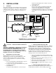
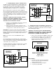
This section provides the recommended procedures for properly
installing the AQUASWITCH I Controller, or AQUASWITCH
II Monitor/controller, Valve(s), and Sensor. Figure II.A.1 gives
an overview of the entire system. Alternate configurations on
page 39.
!
CAUTION - READ FOLLOWING CAREFULLY
WARNING: THE MYRON L COMPANY RECOMMENDS
THAT ALL MOUNTING AND ELECTRICAL
INSTALLATIONS BE PERFORMED BY QUALIFIED
PERSONNEL ONLY. FAILURE TO DO SO COULD
CAUSE DAMAGE TO INSTRUMENT, AND COULD BE
HARMFUL OR FATAL TO PERSONNEL.
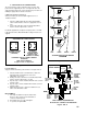
B. MECHANICAL INSTALLATION
All AQUASWITCH electronics are packaged inside
drip/weather-proof housings. The physical dimensions of the
housing is suitable for panel, bench or surface mounting.
There are four basic guidelines to consider when selecting a
mounting location:
1. Select a site that limits the AQUASWITCH‘s exposure
to excessive moisture and corrosive fumes.
2. If at all possible, mount the AQUASWITCH at eye level
for viewing convenience.
3. AQUASWITCH I
If needed, the AQUASWITCH I enclosure may be
rotated or mounted upside down so that the cutouts are
on the opposite side.
4. AQUASWITCH II
For best results, position your Monitor/controller and
sensor as close as possible to the point(s) being
controlled. The AQUASWITCH II Resistivity &
Conductivity/TDS Monitor/controllers are not designed to
operate with a sensor cable length that exceeds 100' (30
meters).
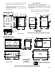
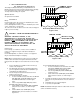
1. SURFACE MOUNTING WITH SMP
NOTE: A Surface Mounting Plate (AQUASWITCH I - #SMP50)
or (AQUASWITCH II - #SMP60) may be required when access
to the back side of the mounting site is impractical or if the
AQUASWITCH must be mounted on a solid wall. Both SMP’s
come with the proper hardware to mount the AQUASWITCH to
the SMP, however, the installer must provide the four (4)
additional screws/bolts to mount the SMP to the wall or fixture.
Their type and size is to be determined by the user.
1. Select your mounting location. Mark and drill the four (4)
required mounting holes. For hole locations, use the SMP
as a template.
2. Drill the corner holes in the SMP according to the size of
the screws or bolts selected.
3. Attach and securely fasten the SMP to the Monitor using
the 1/4" X 20 X 3/8" screws provided.
4. Mount the SMP to the prepared site using the selected
screws or bolts.
2. SURFACE MOUNTING WITHOUT SMP
NOTE: Surface mounting will require two (2) 1/4 " X 20 screws of
a length equal to the thickness of the mounting site plus 3/8"
9
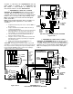
Figure II.A.1.
AQUASWITCH I/II SYSTEMS DIAGRAM
(SEE PAGE 39 FOR ALTERNATIVE CONFIGURATIONS)
AQUASWITCH I
MEGOHMS - CM
750II
MONITOR/CONTROLLER
AQUASWITCH I
BANK A
BANK B
BANK B
PILOT VALVE
BANK A
PILOT VALVE
RESISTIVITY
SENSOR
PROCESS
WATER
OPTIONAL
PROCESS
PILOT VALVE
(NO)
WASTE
WATER
BLEED
PILOT VALVE
(NC)
WASTE WATER
SOURCE
WATER
NC
NC
ALARM
RELAY
VAC
DIDI DI
DIDI DI
AQUASWITCH II
AQUASWITCH II