
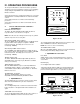
Instruction Manual

!
CAUTION - READ FOLLOWING CAREFULLY
B. SETUP PROCEDURES
These Setup procedures cover (1) converting the alarm circuit to
trigger on a decreasing (conductivity) or increasing (Resistivity)
reading, (2) setting the alarm circuit set point, and (3) adjusting
the hysteresis.
The following require that the front panel be removed. While doing
so be careful not to strain the cable(s).
NOTE: A small screwdriver or tweaker will be required for several
of the following operations.
1. SET POINT CONVERSION (SPC) /
REVERSING SET POINT
The alarm/control circuit on all Resistivity AQUASWITCH II
Monitor/controllers are configured to trigger the alarm relay as the
Resistivity reading decreases.
The alarm/control circuit on all Conductivity/TDS AQUASWITCH
II Monitor/controllers are configured to trigger the alarm relay as
the conductivity/TDS reading increases.
If the user's application requires it, the alarm circuit may be easily
reconfigured to trigger the alarm relay as the conductivity (or
ppm) reading decreases or increases for Resistivity. Refer to
figure V.A.1. for the locations of the jumpers referred to in this
section.
NOTE: These instructions describe the general procedures for
converting the AQUASWITCH II Monitor/controller without
reference to jumper numbers or orientation.
1. Ensure power is OFF.
2. Locate the jumper block for the alarm to be configured.
3. Make a note of the current orientation of the jumpers.
4. Remove both jumpers. This is easily done by hand. Take
care not to crush the jumpers if using pliers.
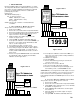
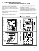
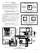
5. Rotate the jumpers 1/4 turn and reinstall them on their
posts as shown in figure IV.B.1.
2. SET POINT ADJUSTMENT
The set point setting is based upon the user's particular water
purity specifications or requirements.
1. Being careful not to strain the cable, unfasten and
remove the Monitor's front panel.
2. While depressing the "SET POINT" switch, turn
the Set Point #1 adjustment screw (See figure V.A.1)
until the desired set point value is indicated on the
display.
3. If Hysteresis adjustment is required see below. If not,
reinstall the front panel and tightly secure both retaining
screws.
3. HYSTERESIS (DEAD BAND) ADJUSTMENT
The hysteresis or dead band is approximately ±3% of the set point
at full scale as it leaves the factory. Under normal (most)
conditions it will not be necessary to adjust.
However, if you desire to make an adjustment please keep the
following in mind.
The adjustment is very simple and is based on set point location.
If the set point* is in the upper 75-100% of the scale, the
hysteresis control pot should be turned fully to the right.
If the set point is in the lower portion of the scale, i.e. 5-25% of
scale, the control pot may be turned fully to the left.
If you are operating in the center, 25-75% of scale, the the control
pot may be adjusted in the center.
Or the hysteresis or dead band may be adjusted to tighten the
control of a particular process.
CAUTION: adjusting the hysteresis too tight may cause the
alarm to fluctuate (on-off) due to flow, chemical mixing or bubbles
causing the relay to chatter. This condition is to be avoided, it
could damage your valves, pumps, etc. and will eventually
damage the relay.
The following is assuming the front panel is already removed and
the set points have been set, if not see above.
1. Locate the hysteresis control adjustment located next to
the Set Point #1 (SP1) adjustment - it is a single turn pot.
See figure V.A.1.
2. Adjust as described above or as desired.
C. OPERATIONAL CHECKOUT PROCEDURES
The following checkout procedures are used to verify that the
AQUASWITCH I or AQUASWITCH II is operating properly.
To complete the checkout procedure, it is assumed that the
system is fully installed and the AQUASWITCH I is connected
to a reliable Monitor/controller or an AQUASWITCH II is
installed. It is also assumed that two fresh Dl banks or RO system
are on line with the system and the Monitor/controller is indicating
water quality in the desired range.
During this test procedure, it will be necessary to simulate GOOD
and POOR water quality. This is done by setting the Set Point to
BELOW or ABOVE the Monitor/controller’s actual water reading.
When the Set Point is set BELOW (counterclockwise), the monitor
will simulate “GOOD” water quality. “POOR” water quality is
simulated by setting the Set Point ABOVE (clockwise) the actual
water quality.
1. AQUASWITCH II (ONLY)
For AQUASWITCH II users, the term “Controller” refers to the
ASII Monitor/controller Circuit Board functions.
33
JUMPER CONVERSION
Figure IV.B.1
INCREASING DECREASING
CONDUCTIVITY/TDS
DECREASING INCREASING
RESISTIVITY