
User guide


V. SOLUTION SELECTION
A. Why Solution Selection is Available
Conductivity and TDS require temperature correction to 25°C values (ref.
Standardized to 25°C, pg. 15). Selection determines the temperature
correction of conductivity and calculation of TDS from compensated
conductivity (ref. Conductivity Conversion to TDS, pg. 17).
B. The 3 Solution Types
On the left side of the display is the salt solution characteristic used to
model temperature compensation of conductivity and its TDS
conversion. Generally, using KCl for conductivity and 442 (Natural Water
characteristic) for TDS will reflect present industry practice for
standardization. Your instrument as shipped from the factory is set for
conductivity with the KCl tempco. If you are measuring natural waters and
wish to have maximum accuracy, it may be better to change it to the 442
setting. However, selecting NaCl for either conductivity or TDS may best
reflect your specific specialized needs (ref. Solution Characteristics, pg.
17).
C. Procedure to Select a Solution
NOTE: Check display to see if solution displayed (KCl, NaCl or 442) is
already the type desired. If not:
1. Dry Instrument THOROUGHLY.
2. Remove the 4 bottom screws and carefully open Instrument.
3. Locate dip switch labeled “TEMP COMP” on the right side of the
circuit board. Switch positions are 1-4 (left to right).
4. Set switch numbers 1 and 2 to the desired position.
Note: Factory setting is for KCl - both switches UP or ON.
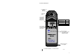
5. Carefully turn instrument over and press the key. The
correct icon “KCl”, NaCl” or “442” should be shown on the left
side of the display.
6. Replace bottom, ensuring the sealing gasket is installed in the groove
of the top half of case. Tighten screws securely. (Do NOT overtighten)
7. Recalibrate as necessary. See Calibration, pg. 9.
D. Procedure to Select the Units of Measurement
i.e., µS to ppm
1. Dry Instrument THOROUGHLY.
2. Remove the 4 bottom screws and open Instrument.
3. Locate dip switch labeled “TEMP COMP” located on the right
side of the circuit board. Switch positions are 1-4 (left to right).
4. Set switch number 3 to the desired position - COND or TDS.
Note: Factory setting is for COND - DOWN or OFF.
5. Carefully turn instrument over and press the key. The
correct icon “µS” or “PPM” should be shown on the right side of
the display.
6. Replace bottom, ensuring the sealing gasket is installed in the groove
of the top half of case. Tighten screws securely. (Do NOT overtighten)
7. Recalibrate as necessary. See Calibration Procedures, pg. 10.
VI. CALIBRATION
A. Calibration Intervals
Generally, calibration is recommended about once per month with
Conductivity or TDS solutions.
B. Rules for Calibration in the AR1
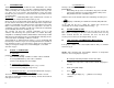
1. Calibration Steps
The calibration is accomplished by a Calibration Control located under the
respective cap plug located on the bottom of the instrument.
After pressing the COND/TDS key, the reading is changed/adjusted to
match the known standard value.
2. Calibration Limits
In Conductivity or TDS, the inability to calibrate may indicate improper or
contaminated calibration solution, or a damaged conductivity cell.
8 9
In the first five sections, you have learned all
you need to make accurate measurements.
The following sections contain calibration,
advanced operations, and technical information.
COND
TDS
COND
TDS