TechPro™ Operation Manual Model pH1 MYRON L COMPANY 10-02 (WEB) EG
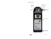
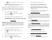
Instrument Illustration pH Sensor (User replaceable) Reference Junction (under Glass Bulb) pH Glass Electrode pH Sensor Protective Cap Temperature Sensor LO BATT °C pH Measurement key pH pH Meter pH1 MYRON L COMPANY Wrist/neck strap slot (user supplied) For detailed explanations, see Table of Contents 10-26-98 1
FEATURES and SPECIFICATIONS • • • • • • • A. Features Superior resolution 3 1/2 digit LCD Accuracy of ± .05 pH units All electrodes are internal for maximum protection Latest sensor technology Water resistant Easy calibration Temperature Accuracy of ±1° C/F B. General Specifications Display Dimensions (LxWxH) Weight Case Material pH Sensor Well Capacity Power Battery Life Operating/Storage Temperature Protection Ratings 3 1/2 Digit LCD 7.7x2.7x2.5 in. 196x68x64 mm 10.8oz./310g ABS 0.04 oz./1.
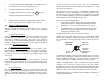
TABLE OF CONTENTS X. ACCESSORIES . . . . . . . . . . . . . . . . . . . . . . . . . . . . . . . . . . . . . . . . 13 A. pH Buffer Solutions . . . . . . . . . . . . . . . . . . . . . . . . . . . 13 B. pH Sensor Storage Solution. . . . . . . . . . . . . . . . . . . . 13 C. Soft Protective Case . . . . . . . . . . . . . . . . . . . . . . . . . . 13 D. Replacement pH Sensor . . . . . . . . . . . . . . . . . . . . . . 13 E. Conductivity/TDS Standard Solutions . . . . . . . . . . . 13 XI. pH MEASURING . . . .
I. INTRODUCTION Thank you for selecting the TechPro™ Series, Model pH1, one of the Myron L Company’s latest in a new line of digital instruments utilizing advanced circuitry. This circuitry makes it very accurate and easy to use (see pages 2 & 3 for Features and Specifications on this and other models). For your convenience, on the bottom side of your pH1 is a brief set of instructions. 4. Press pH . 5. Take reading. 6.
4. 5. Press pH to verify the pH calibration. (If the display reads 7.00, skip the pH Zero Calibration and proceed to section b. pH Gain Calibration. If reading is not acceptable, continue. 7. If the instrument will be used to read both acids and bases, repeat steps 1 and 6 using opposite buffer solution. Remove cap plug labeled ZERO CAL on bottom of Instrument. 8. If reading is different by more than is acceptable, split the difference with the previous setting.
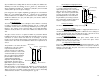
3. Locate dip switch labeled “TEMP COMP” on the right side of the circuit board. Note: Factory setting is degrees “C”. 4. Set switch number 4 to the down position. 5. Carefully turn instrument over and press the pH key. The displayed reading will be in Fahrenheit “°F”. 6. Replace bottom, ensuring the sealing gasket is installed in the groove of the top half of case. Tighten screws securely. VIII. CARE and MAINTENANCE The pH1 should be rinsed with clean water after each use.
Symptom Battery weak or not connected. Possible Cause TROUBLESHOOTING CHART No display, even though measurement key pressed. IX. Inaccurate pH readings 1. pH calibration needed. (ref. Calibration Procedure, pg. 7) 2. Cross-contamination from residual pH buffers or samples in sensor well. 3. Calibration with expired pH buffers. No response to pH changes Sensor bulb is cracked or an electromechanical short caused by an internal crack. Will not adjust down to pH 7. pH sensor has lost KCl.
(H+) ions will increase acidity, while an increase in (OH -) ions will increase alkalinity. The total concentration of ions is fixed as a characteristic of water, and balance would be 10 -7 mol/liter (H +) and (OH- ) ions in a neutral solution (where pH sensors give 0 voltage). pH is defined as the negative logarithm of hydrogen ion concentration. Where (H+ ) concentration falls below 10 -7, solutions are less acidic than neutral, and therefore are alkaline.
XII. GLOSSARY Logarithm - NOTES An arithmetic function. See pH Units, pg. 13. For details on specific areas of interest refer to Table of Contents.