iVECTOR HEATER/COOLER iV080, iV100, iV120, iV140, iV160 2 AND 4-PIPE MODELS. INSTALLATION, OPERATING, MAINTENANCE & AFTER SALES MANUAL Product Serial Number: Please leave this manual with the end user. Part Number: 1370071 heatingthroughinnovation.
1.0 Introduction 03 2.0 Warnings & Safety Measures 03 3.0 Heating System Design 03 4.0 Unit Selection/Sizing 04 5.0 Location 04 6.0 Preparation 05 7.0 Fixing 06 8.0 Water Connection 07 9.0 Electrical Connection 10 10.0 Commissioning Procedure 14 11.0 Technical Data 15 12.0 Control System Set-up and Operating Instruction 17 12.1 Unit Operation 17 12.2 Operating Modes 19 12.3 Installer’s Set-up Parameters 20 12.4 Building Management System Input Set-up 20 12.
iVECTOR Heater/Cooler 03 A range of accessories are available for this product including control valves and condensate pumps for cooling installations (see Section 15). 2.0 The control system provides thermostatic room temperature and automatic fan speed control, and allows operation on a stand-alone basis, or by integration into building management systems. The unit is fitted with a washable air filter that can be easily removed for cleaning (see Section 14). 3.
04 iVECTOR Heater/Cooler 3.0 Heating System Design (continued...) Note: Pressure independent balancing and control valve kits are available for this product as an accessory. These valve kits can simplify system design by eliminating the possible need for larger balancing valves elsewhere in the system, and will maintain the flow in the unit to the required levels. See accessories section for more details (Section 15). NB: Pipes should be sized using flow rate and pressure losses.
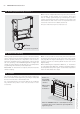
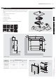
iVECTOR Heater/Cooler 05 6.0 Preparation Before proceeding with the installation, remove the carton lid, unpack the contents carefully and check against the checklist below: 1. Heater/Cooler unit (chassis) 2. Outer Casing 3. Warranty Card 3.0 1 4. Instruction Manual 5. Fixing kit Check contents for concealed shipping damage. Tools required: rran Wa ty 4.0 2 3 5.0 4 nu Ma al 6.
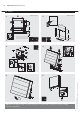
06 iVECTOR Heater/Cooler 7.0 Fixing Dimensions (mm) 1. Dimensions (mm) 2. B 457 236 457 3. 4. 5. 6. NOTE: Do not replace outer cover until connection to system and connection to electrical supply has been completed.
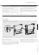
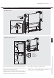
iVECTOR Heater/Cooler 07 8.0 Water Connection Connect the unit to the flow and return pipes, pipework can be routed from the floor or through the wall at the back of the unit. (See options below). Connections are G3/4". needed and can be removed by unscrewing the two bracket fixing screws. Removal of this component will aid pipework fitting when the pipes are routed up from the floor.
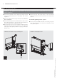
iVECTOR Heater/Cooler 8.0 Water Connection (continued...
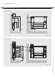
iVECTOR Heater/Cooler 8.0 Water Connection 09 (continued...) How to bleed/vent 8.0 Condensate drain connection Connecting tube >15mm I/D Ensure all water fittings are secure before filling the system. This should be connected to a 15mm drain pipe. Fill the system, open the valves fully and check pipe connections for leaks and vent the heat exchanger. Alternatively a condensate disposal pump is available as an accessory, e.g. for use on internal walls (see Section 15 for accessories).
iVECTOR Heater/Cooler 9.0 Electrical Connection WARNING: This appliance must be earthed. The electrical installation must comply with local or national wiring regulations. l The electrical installation of this appliance should be carried out by a qualified electrician in accordance with current regulations. l Connect the live and neutral wires to the power board terminal connections, and the earth wire to the chassis earth terminal. l This unit is supplied with factory fitted test leads.
iVECTOR Heater/Cooler 9.0 Electrical Connection 11 (continued...) Refer to wiring diagrams below and on page 12-13. 3. Routing cable After making the electrical connections replace the side cover to the control box. 9.
iVECTOR Heater/Cooler 9.0 Electrical Connection (continued...) If you are using the MYSON valve please refer to the Valve Kit Instructions. 2-pipe 1 valve Input* 230V 50Hz + 24V 50Hz 24V DC Supply 230V 50Hz CONTROL BOARD R W Y M+ T+ L N TM- POWER BOARD BR WATER SENSOR 2-PIPE Hi R AIR SENSOR Med W Lo Y FAN BL TRANSFORMER *Voltage free contacts - 230V 50Hz supply needed accross CO+ and COM- to energise actuator. If you are using the MYSON valve please refer to the Valve Kit Instructions.
iVECTOR Heater/Cooler 9.0 Electrical Connection 13 (continued...) If you are using the MYSON valve please refer to the Valve Kit Instructions. 4-pipe 2 valve Input* 230V 50Hz + 24V 50Hz 24V DC CONTROL BOARD POWER BOARD HOT COLD Supply 230V 50Hz R W Y M+ T+ L N TM- WATER SENSOR 4-PIPE COOLING ONLY BR Hi R WATER SENSOR 2-PIPE Med W AIR SENSOR Lo Y FAN BL TRANSFORMER If you are using the MYSON valve please refer to the Valve Kit Instructions. 4-pipe 2 valve + BMS 24V AC 9.
iVECTOR Heater/Cooler 10.0 Commissioning Procedure 1 1. l Fill and vent the system. l Open all valves fully and vent air from the heat exchanger. l Check for leaks at pipe connections. 2. l Refit the outer casing and secure with the 2 screws. l Switch on the electrical supply. l Check the operation of the unit by following the operating instructions. 3. l Set up the installation parameters on the controls system as necessary.
iVECTOR Heater/Cooler 15 11.
iVECTOR Heater/Cooler 11.0 Technical Data (continued...) Dimensions Sound Levels Model Nominal Height (mm) Depth (mm) iV60x080 600 iV60x100 600 iV60x120 iV60x140 iV60x160 Sound Pressure (dBA) (at 2.5m) Length (mm) Model 153 800 iV60x080 24.8 37.7 47.9 153 1000 iV60x100 27 35.8 47.9 600 153 1200 iV60x120 24 40.5 51.7 600 153 1400 iV60x140 24.9 35.5 54.8 600 153 1600 iV60x160 27 35 56.3 Normal Medium Boost Sound levels tested in accordance with ISO 3741.
iVECTOR Heater/Cooler 17 12.0 Control System Set-up and Operating Instruction General Description Additional functions are available if necessary from the Full operating mode menu. The electronic control system on this unit provides a wide range of options that can be selected according to system complexity and operating requirements. A range of additional parameters and features can be changed or activated in a further set up menu should these be required.
iVECTOR Heater/Cooler 12.1 Unit Operation (continued...) Easy Mode Display 1. Heating indicator 2. Cooling indicator 3. Temperature symbol – when this is displayed the current room temperature is displayed 4. Fan speed symbol (fan blades will rotate when active) 5. Comfort setting 6. Power (on/off) 7. Clock setting 8. Room temperature 9. Time 10. Day of the week Keys: OK + - Validation key (OK) Plus key (up) Minus key (down) Navigation left Navigation right Full Mode Display 1.
iVECTOR Heater/Cooler 19 12.2 Operating Modes Use ( ) and ( ) keys to choose from the following parameters. A function is selected when the icon is surrounded by . Control Operation Setup Control Operation Setup The unit must be programed for operation in heating only, cooling only or heating and cooling. Scroll to the Fixed Fan mode , and then press on the ( ) key. Use (+) or (-) keys to choose from the following: Nod (Mode) HOt for heating. Nod (Mode) COLd for cooling.
iVECTOR Heater/Cooler 12.3 Installer’s Set-up Parameters The various parameters that can be defined by the installer are shown in the table below. To access the installation parameters menu, scroll to AUTO, then press (OK) for 10s. Use ( ) and ( adjusted. Parameter Name dEG 00:00 ) keys to highlight the parameter to be Press (OK) to toggle the parameter setting or edit the value. If the value starts to blink, use (+) and (-) keys to adjust the value.
iVECTOR Heater/Cooler 21 12.5 Program Mode P Program Menu A quantity of 9 built-in (P1 - P9) and 4 user defined (U1 - U9) timed program options are available to choose from. Each day is divided into 24 one hour periods operating in either Comfort setting (21°C default) or Night set-back setting (19°C default). Use the (+) and (-) keys to scroll through the program options. 1. Built-in Program Selection Scroll to the preferred program number P1 to P9 - the number will flash. Press (OK) to confirm.
iVECTOR Heater/Cooler 13.0 Troubleshooting Please follow the troubleshooting guide below before calling for assistance. It is important to make sure that an apparent problem with this unit is not the result of system controls being Problem Heating Mode/ Cooling Mode No Fan incorrectly set, that there is no electrical supply to the unit or that the unit is incorrectly set.
iVECTOR Heater/Cooler 23 14.0 Maintenance Disconnect from the power supply before carrying out maintenance work. Maintenance should be restricted to occasional removal of dust and lint around the unit. The outer surface may be wiped over with warm water and mild detergent taking care to avoid water entering the grille areas. Replacing the Filter Periodically the filter will need to be cleaned, and the control system on this product will display ‘FILT’ when it is time for the filter to be checked.
iVECTOR Heater/Cooler 24 16.0 Spare Parts Spare Parts Item Description Model Part No.
MYSON Eastern Avenue, Team Valley, Gateshead, Tyne & Wear NE11 0PG, UK T: 0845 402 3434, F: 0191 491 7568, sales@myson.co.uk, www.myson.co.uk After Sales Service: MYSON Service, Somerden Road, Hull, East Yorkshire HU9 5PE T: 01482 713927, F: 01482 789056, service.convectors@myson.co.uk iVECTOR HEATER/COOLER INSTALLATION, OPERATING, MAINTENANCE & AFTER SALES MANUAL 01 02 2015 ISSUE 3 Spare parts and technical help on all Convector products are available from MYSON Service. heatingthroughinnovation.