25278 iVector Installation Guide US 02/01/2013 09:24 Page 2 iVECTOR HEATER/COOLER 2 AND 4-PIPE MODELS. INSTALLATION, OPERATING, MAINTENANCE & AFTER SALES MANUAL JANUARY 2013, ISSUE 1 Product Serial Number: Please leave this manual with the end user. Part Number: 1371060 heatingthroughinnovation.
5278 iVector Installation Guide US 02/01/2013 09:24 Page 3 Contents 1.0 Introduction 03 2.0 Warnings & Safety Measures 03 3.0 Heating System Design 03 4.0 Unit Selection/Sizing 04 5.0 Location 04 6.0 Preparation 05 7.0 Fixing 06 8.0 Water Connection 07 9.0 Electrical Connection 10 10.0 Commissioning Procedure 14 11.0 Technical Data 15 12.0 Control System Set-up and Operating Instruction 17 12.1 Unit Operation 17 12.2 Operating Modes 19 12.
25278 iVector Installation Guide US 02/01/2013 09:24 Page 4 iVECTOR Heater/Cooler 03 A range of accessories are available for this product including control valves and condensate pumps for cooling installations. The control system provides thermostatic room temperature and fan speed control, and allows operation on a stand alone basis, or by integration into building management systems. This manual should be read carefully prior to installation and retained for future reference. 2.
25278 iVector Installation Guide US 02/01/2013 09:24 Page 5 04 iVECTOR Heater/Cooler 3.0 Heating System Design (continued...) Note: Pressure independent balancing and control valve kits are available for this product as an accessory. The valve kits can simplify system design by eliminating the possible need for larger balancing valves elsewhere in the system, and will maintain the flow in the unit to the required levels. See accessories section for more details.
25278 iVector Installation Guide US 02/01/2013 09:24 Page 6 iVECTOR Heater/Cooler 05 6.0 Preparation Before proceeding with the installation, remove the carton lid, unpack the contents carefully and check against the checklist below: 1. Heater/Cooler unit (chassis) 2. Outer Casing 3. Warranty Card 1 3.0 4. Instruction Manual 5. Fixing kit Check contents for concealed shipping damage. 2 3 4.0 ty rran Wa Tools required: 4 5.0 l nua Ma 6.
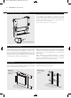
25278 iVector Installation Guide US 02/01/2013 09:24 Page 7 06 iVECTOR Heater/Cooler 7.0 Fixing 1. 2. B 18 9 9/32" 18 9 9/32" 3. 4. 5. 6. NOTE: Do not replace outer cover until connection to system and connection to electrical supply has been completed.
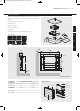
25278 iVector Installation Guide US 02/01/2013 09:24 Page 8 iVECTOR Heater/Cooler 07 8.0 Water Connection Connect the unit to the supply and return pipes. Pipework can be routed from the floor or through the wall at the back of the unit. (See options below). Connections are 3/4"bsp. needed and can be removed by unscrewing the two bracket fixing screws. Removal of this component will aid pipework fitting when the pipes are routed up from the floor.
25278 iVector Installation Guide US 02/01/2013 09:25 Page 9 08 iVECTOR Heater/Cooler 8.0 Water Connection (continued...
25278 iVector Installation Guide US 02/01/2013 09:25 Page 10 iVECTOR Heater/Cooler 8.0 Water Connection 09 (continued...) How to bleed/vent 8.0 Condensate drain connection Spiggot size 1 9/32" O/D Connecting tube >1 9/32" I/D Ensure all water fittings are secure before filling the system. This should be connected to a 1/2" drain pipe. Fill the system, open the valves fully and check pipe connections for leaks and vent the heat exchanger.
25278 iVector Installation Guide US 02/01/2013 09:25 Page 11 10 iVECTOR Heater/Cooler 9.0 Electrical Connection WARNING: This appliance must be grounded. The electrical installation must comply with state or local codes. l The electrical installation of this appliance should be carried out by a qualified electrician in accordance with current regulations. l This unit is supplied with factory fitted 3 core cord, 6ft in length with moulded plug. 1.
25278 iVector Installation Guide US 02/01/2013 09:25 Page 12 iVECTOR Heater/Cooler 9.0 Electrical Connection 11 (continued...) Refer to wiring diagrams below and on page 12-13. 3. Routing cable After making the electrical connections replace the side cover to the control box.
25278 iVector Installation Guide US 02/01/2013 09:25 Page 13 12 iVECTOR Heater/Cooler 9.0 Electrical Connection (continued...
25278 iVector Installation Guide US 02/01/2013 09:25 Page 14 iVECTOR Heater/Cooler 9.0 Electrical Connection 13 (continued...) 4-pipe 2 valve Input 120V 60Hz + 24V 60Hz - POWER BOARD CONTROL BOARD 24V DC HOT COLD Supply 120V 60Hz R G Y M+ T+ L N TM- WATER SENSOR 4-PIPE COOLING ONLY B Hi R WATER SENSOR 2-PIPE Med G Lo Y AIR SENSOR FAN W TRANSFORMER 9.
25278 iVector Installation Guide US 02/01/2013 09:25 Page 15 14 iVECTOR Heater/Cooler 10.0 Commissioning Procedure 1 2 1. l Fill and vent the system. l Open all valves fully and vent air from the heat exchanger. l Check for leaks at pipe connections. 2. l Refit the outer casing and secure with the 2 screws. l Switch on the electrical supply. l Check the operation of the unit by following the operating instructions. 3. l Set up the installation parameters on the controls system as necessary.
25278 iVector Installation Guide US 02/01/2013 09:25 Page 16 iVECTOR Heater/Cooler 15 11.0 Technical Data Performance Data 2-Pipe Model iV60x080 iV60x100 iV60x120 iV60x140 iV60x160 Fan Speed Heat Output (Btu/h) Flow (gpm) Cooling (Btu/h) 110 120 Entering Water - 65°F Air Temperature 130 140 150 160 170 180 Condition 45-54-81 190 200 Total Sensible Normal 1.5 3051 3791 4543 5304 6073 6850 7634 8423 9219 10020 2412 1798 Medium 1.
25278 iVector Installation Guide US 02/01/2013 09:25 Page 17 16 iVECTOR Heater/Cooler 11.0 Technical Data (continued...) Dimensions Weight, Water Content and Motor Power Model Motor Power (w) 2 Pipe Water Content (gal) 39 3/8 iV60x080 32 0.174 0.087 50 115 6 47 1/4 iV60x100 35 0.243 0.1215 61 140 iV60x140 23 5/8 6 55 1/8 iV60x120 44 0.314 0.6 72 164 iV60x160 23 5/8 6 63 iV60x140 53 0.383 0.73 83 189 iV60x160 65 0.454 0.
25278 iVector Installation Guide US 02/01/2013 09:25 Page 18 iVECTOR Heater/Cooler 17 12.0 Control System Set-up and Operating Instruction General Description Additional functions are available if necessary from the Full operating mode menu. The electronic control system on this unit provides a wide range of options that can be selected according to system complexity and operating requirements.
25278 iVector Installation Guide US 02/01/2013 09:25 Page 19 18 iVECTOR Heater/Cooler 12.1 Unit Operation (continued...) Easy Mode Display 1. Heating indicator 2. Cooling indicator 3. Temperature symbol – when this is displayed the current room temperature is displayed 4. Fan speed symbol (fan blades will rotate when active) 5. Comfort setting 6. Power (on/off) 7. Clock setting 8. Room temperature 9. Time 10.
25278 iVector Installation Guide US 02/01/2013 09:25 Page 20 iVECTOR Heater/Cooler 19 12.2 Operating Modes Use ( ) and ( ) keys to choose from the following parameters. A function is selected when the icon is surrounded by . Description Control Operation Setup Control Operation Setup The unit must be programed for operation in heating only, cooling only or heating and cooling. Scroll to the Fixed Fan mode , and then press on the ( ) key.
25278 iVector Installation Guide US 02/01/2013 09:25 Page 21 20 iVECTOR Heater/Cooler 12.3 Installer’s Set-up Parameters The various parameters that can be defined by the installer are shown in the table below. To access the installation parameters menu, scroll to Auto, then press (OK) for 10 seconds. Use ( ) and ( adjusted. Parameter Name dEG 00:00 ) keys to highlight the parameter to be Press (OK) to toggle the parameter setting or edit the value.
25278 iVector Installation Guide US 02/01/2013 09:25 Page 22 iVECTOR Heater/Cooler 21 12.5 Program Mode P Program Menu A quantity of 9 built-in (P1 - P9) and 4 user defined (U1 - U9) timed program options are available to choose from. Each day is divided into 24 one hour periods operating in either Comfort setting (21°C default) or Night set-back setting (19°C default). Use the (+) and (-) keys to scroll through the program options. 1.
25278 iVector Installation Guide US 02/01/2013 09:25 Page 23 22 iVECTOR Heater/Cooler 13.0 Troubleshooting Please follow the troubleshooting guide below before calling for assistance. It is important to make sure that an apparent problem with this unit is not the result of system controls being Problem Heating Mode/ Cooling Mode No Fan incorrectly set, that there is no electrical supply to the unit or that the unit is incorrectly set.
25278 iVector Installation Guide US 02/01/2013 09:25 Page 24 iVECTOR Heater/Cooler 23 14.0 Maintenance Disconnect from the power supply before carrying out maintenance work. Maintenance should be restricted to occasional removal of dust and lint around the unit. The outer surface may be wiped over with warm water and mild detergent taking care to avoid water entering the grille areas.
25278 iVector Installation Guide US 02/01/2013 09:24 Page 1 MYSON INC 49 Hercules Drive, Suite 4904, Colchester VT0446 T: 802 654 7500, F: 802 654 7022, info@mysoninc.com, www.mysoninc.com 01.01.2013 ISSUE 1 heatingthroughinnovation.