
Technical data

03
KICKSPACE
®
500E
5.0 Technical Data
6.0 Operating Instructions
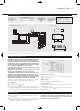
Fan
br
bl
g/y
Thermal Trip
Electric Element
Heating Switch
Power Selector
Switch
Fan Speed
Switch
View Switches
from Front
bl
br
p
br
br
y
g/y
r
r
p
p
y
br
br
bl
y
NL
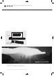
Dimensions (mm)
7.0 Maintenance
l Before undertaking any maintenance activity isolate the
electrical supply.
l Maintenance should be restricted to occasional removal of
dust and lint around the front grille. Any further maintenance
should be carried out by a qualified engineer.
WARNING: IF THE SUPPLY CORD IS DAMAGED IT MUST BE
REPLACED BY THE MANUFACTURER, ITS SERVICE AGENT
OR OTHER RESPONSIBLE PERSON.
WARNING: THIS APPLIANCE IS NOT INTENDED FOR USE BY
PERSONS (INCLUDING CHILDREN) WITH REDUCED PHYSICAL,
SENSORY OR MENTAL CAPABILITIES, LACK OF EXPERIENCE OR
KNOWLEDGE, UNLESS THEY HAVE BEEN GIVEN SUPERVISION
OR INSTRUCTION CONCERNING THE USE OF THE APPLIANCE
BE A PERSON RESPONSIBLE FOR THEIR SAFETY.
CHILDREN SHOULD ALSO BE SUPERVISED SO THAT THEY DO
NOT PLAY WITH APPLIANCE.
WARNING: DO NOT COVER THE UNIT OR OBSTRUCT THE
GRILLE AREA. IF COVERED THERE IS A RISK OF FIRE.
WARNING: THIS HEATER IS NOT EQUIPPED WITH A DEVICE TO
CONTROL THE ROOM TEMPERATURE. DO NOT USE THIS
HEATER IN SMALL ROOMS WHEN THEY ARE OCCUPIED BY
PERSONS NOT CAPABLE OF LEAVING THE ROOM ON THEIR
OWN, UNLESS CONSTANT SUPERVISION IS PROVIDED.
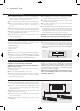
This unit is controlled by the switches on the front of the unit
(see fig. 3). Ensure the electricity supply is switched on.
Heating Mode
l Set the fan switch to position.
l Set the power switch to the I or II position as required. The fan
will operate at the appropriate speed for the element selected.
The fan speed switch does not operate in these Conditions.
Temperature Control
Use the Power switch I or II to increase or decrease the heat
output, as required.
Off Position
Set the Heating switch to the (O) position.
Summer Mode
If required, the KICKSPACE
®
can be used in Summer for air
circulation without heat.
Set the heating switch to position,and set the fan speed to
required setting.
Key:
br - Brown
bl - Blue
r - Red
p - Purple
y - Yellow
g/y - Green/Yellow
Wiring Diagram KICKSPACE
®
500E
321
203
177
Mains Cable
Top view
Cable entries
View on arrow
93
496
101
FRONT GRILLE
N.B: Add 4.5mm to the chassis height to allow for rubber mountings and screws.
Heating Switch
Power Selector
Switch
Fan Speed Switch
Heat Output (kW)
Model
Boost Normal
Supply Cord
Rated Power
(Watts)
500E 2 1 2025 1.0mm
2
Fig. 3
23042 Kickspace Manual 15/02/2012 11:23 Page 4