370036 - 05 ® KICKSPACE 500, 600 and 600-12V FAN CONVECTORS INSTALLATION, MAINTENANCE AND OPERATING INSTRUCTIONS AND TECHNICAL DATA PLEASE READ THESE INSTRUCTIONS THOROUGHLY BEFORE BEGINNING INSTALLATION. AFTER INSTALLATION LEAVE THESE INSTRUCTIONS WITH THE USER AND COMPLETE THE PRODUCT SERIAL NUMBER DETAILS IN THE BOX BELOW. B.E.A.B.
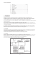
LIST OF CONTENTS 1. 2. Application ............................................................... Page 2 Electrical Supply ................................................................. 3 3. 4. Preparation ......................................................................... 3 Water Connections ............................................................. 4 5. 6. Fitting Kickspace ................................................................. 4 Completion ....................................
2. ELECTRICAL SUPPLY WARNING: THIS APPLIANCE MUST BE EARTHED. The electrical installation must comply with local or national Regulations. 2.1 The Kickspace is supplied fitted with a 2 metre 0.75 mm² cord. 2.2 A fused (2A) electrical spur with a switch having 3 mm separation on all poles must be provided in an easily accessible position adjacent to the Kickspace, as shown in Fig. 2.2. 2.3 Room Thermostat - If a room thermostat is to be fitted, wire it at this stage. Remove the link in terminals T1 and T2.
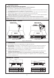
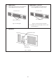
. WATER CONNECTIONS WATER CONNECTIONS - continued 4.1 Connect flexible pipes to the system flow and return pipes. 4.2 Connect the valve ends of the flexible pipes to the rear of the Kickspace. Note: The direction of flow arrows on the valves are not significant in this application. System pipework Flexible pipes Isolating valves Flexible pipes Fig. 4.1 - Connect flexible pipes to system pipework Fig. 4.2 - Connect the flexible pipes to the Kickspace WATER CONNECTIONS - continued 5.
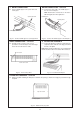
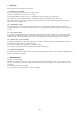
6. COMPLETION COMPLETION - continued 6.1 Align the grille and secure it to the unit with two screws supplied (use the shorter screws). 6.2 Secure the unit/grille to the plinth with two screws supplied (use the longer screws). Front view of unit Front view of unit Unit securing screws Grille securing screws Fig. 6.1 - Fit the grille Fig. 6.2 - Secure the unit to the plinth 6.3 Complete the electrical supply, switch on and test the Kickspace. 7.
8. Operation Ensure that the electrical supply is switched on. 8.1. Winter use - for heating If remote room thermostat is fitted, turn it to a high setting. Set the fan speed switch to Boost or Low, see Fig. 7. Set the Summer/Winter switch, see Fig. 7, to the Winter position by pressing to the red top disc. The fan will now rotate provided hot water is circulating through the heat exchanger at or above 43°C.
10. TECHNICAL DATA Heat outputs with flow rate 75 g/h. Tested in accordance with BS 4856 Pt 1. Model Fan Motor Water power content speed (Watts) (litres) 25 40° 45° Boost 923 Low 50° 55° 60° 65° 72° 81° 90° 99° 108° 117° 1045 1166 1289 1412 1535 3152 3565 3981 4398 4817 5238 733 815 896 1056 1135 2501 2781 3058 3332 3603 3873 Boost 1275 1453 1630 1803 1975 2150 4350 4959 5561 6154 6738 7336 Low 880 1053 1225 1393 1560 1730 3002 3594 4179 4754 5322 5904 0.
CUSTOMER SERVICE INFORMATION After Sales Service A dedicated customer service department backed up by a national network of service engineers is available to support your Myson Convector. Myson service can be contacted by: Customer Service Working Hours: Telephone: 01482 713927 Monday to Thursday 9am to 5pm Facsimile: 01482 789056 Friday 9am to 3pm E-mail: service.convectors@myson.co.