23928 Kickspace Manual_Layout 1 27/06/2011 10:16 Page 2 Installation, Operating, Maintenance and After Sales Manual. KICKSPACE ® 500, 600, 600-12V & 800 heatingthroughinnovation. 01.03.2010 ISSUE 4 Product Serial Number: Please leave this manual with the end user.
3928 Kickspace Manual_Layout 1 27/06/2011 10:16 Page 3 Contents 1.0 General Information 03 2.0 Heating System Design 03 3.0 Selection and Sizing for Heating 03 4.0 Location 03 5.0 Preparation 03 6.0 Electrical Connection 04 7.0 Water Connection 05 8.0 Fitting the KICKSPACE ® 9.0 Technical Data 07 10.0 Operating Instructions 09 11.0 Troubleshooting 10 12.
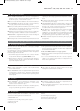
23928 Kickspace Manual_Layout 1 27/06/2011 10:16 Page 4 KICKSPACE ® 500, 600, 600-12V & 800 03 l Before proceeding with the installation, the heating system design must be considered and the unit correctly sized to meet the heat loss requirements of the room. l Flexible hoses with integral isolating valves are supplied to allow easy insallation and future access for maintenance. l KICKSPACE® is supplied with integral controls including fan speed selector and summer/winter switch.
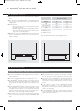
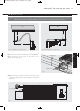
23928 Kickspace Manual_Layout 1 27/06/2011 10:16 Page 5 04 KICKSPACE ® 500, 600, 600-12V & 800 5.0 Preparation (continued...) l A clean and level floor area is required under the cupboard base. l Floor mounting - The is normally fitted directly onto the floor and the base of the unit is fitted with four mounting feet. KICKSPACE® l Plinth mounting • As an alternative to floor mounting the unit may be fitted into the plinth. • A suitable support must be securely fitted to the floor.
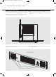
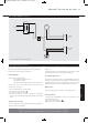
23928 Kickspace Manual_Layout 1 27/06/2011 10:16 Page 6 KICKSPACE ® 500, 600, 600-12V & 800 05 7.0 Water Connection Pipework must be positioned correctly to ensure flexible hoses are not kinked when installed. See Fig. 3. Only use the hose sets supplied with this unit. Do not use old or alternative hose sets. WALL WALL 250 300 400 100 Fig. 3b Right hand view - suggestion only l Connect valve ends of the flexible pipes to the KICKSPACE ®. Flexible pipes 7.
23928 Kickspace Manual_Layout 1 27/06/2011 10:16 Page 7 06 KICKSPACE ® 500, 600, 600-12V & 800 8.0 Fitting the KICKSPACE ® l Position the KICKSPACE® under the cupboard in the required location, with the front edge just behind the line of the plinth. l Ensure that the flexible hoses are not kinked and that the electrical cord is not in contact with hot surfaces. l Replace the plinth and bring the KICKSPACE ® forward into the opening so the front edge projects 8mm through the plinth.
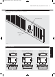
23928 Kickspace Manual_Layout 1 27/06/2011 10:16 Page 8 KICKSPACE ® 500, 600, 600-12V & 800 8.0 Fitting the KICKSPACE ® 07 (continued...) l Complete the electrical installation, switch on and test the KICKSPACE®. Summer/Winter switch Switch for fan Boost Off Normal Fig. 8 9.0 Technical Data 8.
23928 Kickspace Manual_Layout 1 27/06/2011 10:16 Page 9 08 KICKSPACE ® 500, 600, 600-12V & 800 9.0 Technical Data (continued...
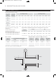
23928 Kickspace Manual_Layout 1 27/06/2011 10:16 Page 10 KICKSPACE ® 500, 600, 600-12V & 800 9.0 Technical Data 09 (continued...) Transformer L MOTOR Mains Supply 240V br N bl br Fan Selector Switch bl Connector Block Summer/Winter Switch LOW LIMIT THERMOSTAT Fig. 11 KICKSPACE® 600-12V wiring diagram 10.0 Operating Instructions This unit is controlled by the switches on the front of the unit, or by means of the wall mounted remote switching kit if fitted.
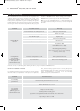
23928 Kickspace Manual_Layout 1 27/06/2011 10:16 Page 11 10 KICKSPACE ® 500, 600, 600-12V & 800 11.0 Troubleshooting installer or MYSON Service. Before calling your installer or MYSON Service, please carry out the checks listed below. Once installed this fan convector becomes an integral part of a complete heating system that includes boiler, pump, other emitters such as radiators and fan convectors, and a number of heating controls, dependent on system complexity.
23928 Kickspace Manual_Layout 1 27/06/2011 10:16 Page 12 KICKSPACE ® 500, 600, 600-12V & 800 11 12.0 Maintenance Before undertaking any maintenance activity isolate the electrical supply. Maintenance should be restricted to occasional removal of dust and lint around the front grille. This should involve internal cleaning of the heat exchanger using a soft brush or vacuum cleaner, taking care not to damage fan or heat exchanger. Please see after sales service details on the back cover.
23928 Kickspace Manual_Layout 1 27/06/2011 10:16 Page 1 MYSON Eastern Avenue, Team Valley, Gateshead, Tyne & Wear NE11 0PG, UK T: 0845 402 3434, F: 0191 491 7568, sales@myson.co.uk, www.myson.co.uk heatingthroughinnovation. After Sales Service: Spare parts and technical help on all Convector products are available from MYSON Service. 01.03.2010 ISSUE 4 MYSON Service, Somerden Road, Hull, East Yorkshire HU9 5PE T: 01482 713927, F: 01482 789056, service.convectors@myson.co.