
Technical data

09
KICKSPACE
®
500, 600, 600-12V & 800
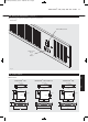
9.0 Technical Data (continued...)
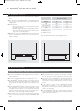
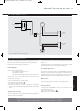
Mains Supply 240V
Transformer
Connector
Block
Fan Selector
Switch
Summer/Winter
Switch
LOW LIMIT
THERMOSTAT
MOTOR
br
bl
L
N
bl
br
Fig. 11 KICKSPACE
®
600-12V wiring diagram
10.0 Operating Instructions
This unit is controlled by the switches on the front of the unit, or
by means of the wall mounted remote switching kit if fitted.
Ensure the electricity supply is switched on.
Heating Mode
The fan will only operate when
• The central heating boiler is on
• The pump is running
• The system water temperature is greater than 43°C.
Ensure boiler is on, and set timer, boiler controls and room
thermostats as necessary.
• Turn room thermostat to a high setting.
• Set summer - winter switch to
• Set fan speed control position I.
• The unit will now run on low fan speed. For satisfactory
operation the mean water temperature should not be below
60°C.
Temperature Control
The room thermostat setting should be gradually adjusted to
obtain the desired temperature.
The fan speed can be set to boost by switching the fan speed
switch to II.
A low speed setting is recommended for normal operation with
the higher speeds for boost heating when required.
Low Limit Operation
The low limit thermostat fitted to the KICKSPACE
®
will ensure
that the fan stops after the heating system is switched off and
the water flow stops. If left in an operating position the unit will
automatically restart when the heating system is reheated.
Off Position
Set the fan speed selector switch to the off (O) position.
Summer Mode
If required, the KICKSPACE
®
can be used in Summer for air
circulation without heat.
Set summer - winter switch to
Adjust fan speed to required setting.
If a remote control switch is fitted, the fan switch on the unit will be inoperative.
Refer to the instructions supplied with the remote control switch for details.
9.010.0
23928 Kickspace Manual_Layout 1 27/06/2011 10:16 Page 10