23678 Lo-Line RC manual UK 27/06/2011 09:28 Page 2 Installation, Operating, Maintenance and After Sales Manual. LO-LINE RC & LO-LINE RC Heater/Cooler Models: 6-4, 9-6, 14-10, 19-15 heatingthroughinnovation. 01.06.2011 ISSUE 5 Product Serial Number: Please leave this manual with the end user.
3678 Lo-Line RC manual UK 27/06/2011 09:28 Page 3 Contents 1.0 General Information 03 2.0 Heating System Design 03 3.0 Unit Selection/Sizing 03 4.0 Location 03 5.0 Preparation 04 6.0 Fixing 04 7.0 Water Connections 05 8.0 Electrical Connection 06 9.0 Commissioning Procedure 06 10.0 Technical Data 08 11.0 Operating Instructions 09 12.0 Troubleshooting 10 13.
23678 Lo-Line RC manual UK 27/06/2011 09:28 Page 4 LO-LINE RC & LO-LINE RC Heater/Cooler 03 Automatic – the desired room temperature is programmed in to the unit and the fan speed is automatically adjusted until the desired room temperature is achieved. l The LO-LINE should only be used on closed circulation, two pipe, pump assisted central heating systems (LO-LINE) or heating and cooling systems (LO-LINE Heater/Cooler).
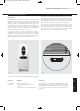
23678 Lo-Line RC manual UK 27/06/2011 09:28 Page 5 04 LO-LINE RC & LO-LINE RC Heater/Cooler 5.0 Preparation Before proceeding with the installation, unpack the carton contents and check against the checklist below: 1. LO-LINE or LO-LINE Heater/Cooler unit. 2. 15mm isolating valves (1 pair). 3. Instruction manual. 4. Warranty card. 5. Fixing kit (rubber mounts and cable gland). 6. Remote control handset. 6.0 Fixing l Using the fixing dimensions (see fig. 1), mark the fixing hole positions on the wall.
23678 Lo-Line RC manual UK 27/06/2011 09:28 Page 6 LO-LINE RC & LO-LINE RC Heater/Cooler 05 7.0 Water Connections l Connect unit to system flow and return pipes using the two 15mm isolating valves (see fig. 3). LO-LINE Heater/Cooler installations with chilled water will require provision for condensate disposal in accordance with any local regulations. Note: To ensure effective venting of the heat exchanger the flow pipe should be connected to the bottom connection of the heat exchanger.
23678 Lo-Line RC manual UK 27/06/2011 09:28 Page 7 06 LO-LINE RC & LO-LINE RC Heater/Cooler 8.0 Electrical Connection WARNING: This appliance must be earthed. The electrical installation must comply with local or national wiring regulations. l This unit is supplied with factory fitted test leads. Remove these and discard. l Connect live and neutral wires to the power board terminal connections, and the earth wire to the chassis earth terminal.
23678 Lo-Line RC manual UK 27/06/2011 09:28 Page 8 LO-LINE RC & LO-LINE RC Heater/Cooler 9.0 Commissioning Procedure 07 (continued...) Heat Pump and Low Water Temperature Systems In heating mode, the control system brings the fan on when the water in the coil reaches 32°C. For low water temperature systems, eg heat pump systems, it is possible to switch off the boost speed option in automatic mode so that the unit runs in medium or normal fan speeds depending on demand.
23678 Lo-Line RC manual UK 27/06/2011 09:28 Page 9 08 LO-LINE RC & LO-LINE RC Heater/Cooler 10.
23678 Lo-Line RC manual UK 27/06/2011 09:28 Page 10 LO-LINE RC & LO-LINE RC Heater/Cooler 09 11.0 Operating Instructions Description This LO-LINE unit is fitted with a control system that provides 3 different operating modes. In automatic mode the desired temperature set point is selected and the unit will adjust the fan speed according to the difference between the actual room temperature and the set point.
23678 Lo-Line RC manual UK 27/06/2011 09:28 Page 11 10 LO-LINE RC & LO-LINE RC Heater/Cooler 11.0 Operating Instructions (continued...) Operation Display Manual Power off No Display Manual mode can be used for air circulation without heat or for manual control of the heating function.
23678 Lo-Line RC manual UK 27/06/2011 09:28 Page 12 LO-LINE RC & LO-LINE RC Heater/Cooler 12.0 Troubleshooting 11 (continued...
23678 Lo-Line RC manual UK 27/06/2011 09:28 Page 1 MYSON Eastern Avenue, Team Valley, Gateshead, Tyne & Wear NE11 0PG, UK T: 0845 402 3434, F: 0191 491 7568, sales@myson.co.uk, www.myson.co.uk Serial Number Location: Inner chassis position heatingthroughinnovation. After Sales Service: Spare parts and technical help on all Convector products are available from MYSON Service. 01.06.2011 ISSUE 5 MYSON Service, Somerden Road, Hull, East Yorkshire HU9 5PE T: 01482 713927, F: 01482 789056, service.