
Manual

JP1 and JP3 - Balanced input at +4dBm (professional level). JP1 and JP3 -these
jumpers insert the 10 turn precision trimpots (RN2 and RN3) for both left and
right analog inputs. These trimpots determine the +4dBm headroom of the
ADC. The setting can be anywhere from -14dBFS to -20dBFS, typical being -
15 or -16 for most of other digital equipment (or -18 to comply with AES level
standard). Refer to “Analog input level” Chapter for alignment procedure
details. These jumpers should normally be removed (retain the jumper on 1 pin
only) if input potentiometer is engaged, but can also be used in parallel with
the pot- using both pot and trimpots will result in lower input sensitivity with
advantage of precise L/R matching.
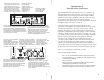
T1 Amp 20mm
Slow Blow fuse
115VAC/230VAC
power switch
JP2 and JP4 -
one
Balanced input at +4dBm (professional level). JP2 and JP4 -
these jumpers insert the input volume conductive plastic potentiometer for both
left and right analog inputs -this setting mimics a typical DAT machine input
volume knob and can be used for remote recording and other applications
where the input level is vaguely defined and needs to be instantly adjusted. The
pot also allows for live fade-in and out. The pot is not recommended for regular
studio use as the L/R sensitivity cannot be set as precisely as with trimpots
because of the mechanical accuracy of the pot. These jumpers should normally
be removed (retain the jumper on pin only) if trimpots are engaged,
although parallel operation is possible (see above)
Jumpers J1 and J2- Set the input to u
Jumpers JP2,JP4,JP1,JP3 should
be removed (retain the jumper on one pin only).
-10dBV (consumer level).
nbalanced. The unbalanced signal should
be fed between pin 2 (signal) and pin 1 (shield) of the input XLR. Pin 3 must be
left unconnected. You can use a standard RCA<>XLR adapter, but make sure
connection to pin 3 is cut inside the adapter.
In this mode the sensitivity of
the input stage is fixed and cannot be adjusted within the converter (adjust level
prior to feeding the converter). This mode is recommended only in situations
when no professional balanced signal source is available. This also works with
Jumper JP5: Wordclock input 75 Ohm termination.
Connect this jumper when Stereo96 ADC is the last destination in a chain fed
by external wordclock source and the cable is long (above 6ft). For short cables
and wordclock sources with unknown drive capability JP5 should be left
unconnected (unterminated) (retain the jumper on one pin only).
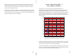
DIPSWITCH SW4 : Sets the clock mode on BNC in/out
SW1- "ON", wordclock =FS/2 for 88.2 and 96k (FS for 44.1 and 48k)
SW2- "ON", output and input becomes Superclock=256 x FS (for use with
Protools(R) Mix systems and 44.1 and 48k only)
SW1- "OFF", wordclock =FS for all sampling rates
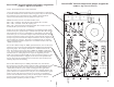
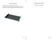
Stereo96ADC internal trimpots and jumper assignments
(remove top cover to access)
Stereo96ADC internal trimpots and jumper assignments
(remove top cover to access)
5
6