8X192 ADDA 8 CHANNEL MASTERING ANALOG TO DIGITAL AND DIGITAL TO ANALOG CONVERTER USER MANUAL VER.
This manual may be updated Download the newest version at: http://www.mytekdigital.com/manuals/8x192adda_manual.pdf For technical support, technical tips and support check: http://www.mytekdigital.com/products/8x192adda.htm or contact Mytek tech support at: info2006@mytekdigital.com or at: tel. (646)-613 1822 fax.
OWNER’S RECORD: The serial number is located on the bottom of the unit. We suggest you record the serial number in the space provided below. The firmware version label is located on the 8 pin emprom chip located in a socket under the top lid. The firmware can be updated and chip replaced by the user if necessary. Please be sure to return your completed warranty card. 8x192 ADDA Serial NO.
Introduction.....................................................…………………………….5 Signal Flow...............................…………………………………….............6 Block Schematics...........................................................................……...7 Back Panel Connections, Cable Wiring.........................................……...8 Front Panel Controls................................................……………...………9 Input/output Gain and other internal adjustments.....……......................
INTRODUCTION Mytek 8X192 ADDA is an 8 channel Analog to Digital and an 8 channel Digital to Analog converter maticoulsly designed to provide the highest quality signal path. No compromises have been made to sound quality, and we feel that this is the best sounding Mytek converter to date. In trial tests in comparison with other hi-end brands this unit provided the same or better sonic performance, which makes it suitable for the most demanding mastering and recording applications.
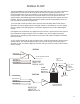
SIGNAL FLOW The 8X192 ADDA has two independent signal paths within the unit. They offer independent signal paths but must operate at the same clock source and sampling frequency. It's recommended that as much as possible the unit should be clocked from its internal CX 797 clock generator. This mode offers minimum jitter allowin for the best performance and system stability. Associated equipment should be slaved to 8X192 clock outputs whenever possible.
HEADPHONE AMP SUMM. BUS/ PAIR MONITOR SELECTOR STEPPED 1 dB ATTENUATOR AN. IN 1-8 (BOTT) JUMPER FIXED GAIN -15dBFS (DEFAULT) VAR.GAIN (UNDER HOOD) VAR.GAIN (UNDER HOOD) AN.OUT 1-8 (TOP) PROTOOLS HD, FIREWIRE, ADAT, TDIF, DSD, SONIC HD CARDS ARE AVAILABLE JUMPER FIXED GAIN -15dBFS (DEFAULT) VAR.GAIN (UNDER HOOD) JUMPER FIXED GAIN -15dBFS (DEFAULT) VAR.GAIN (UNDER HOOD) INPUTS 1-8 PROTOOLS HD, FIREWIRE, ADAT, TDIF, DSD, SONIC HD CARDS ARE AVAILABLE JUMPER FIXED GAIN -15dBFS (DEFAULT) VAR.
AN.OUT 1-8 (TOP) - + - + - + - + - + - + - + Analog input and output DB25 pinout corresponds to standard used by Protools, Tascam, Radar and Apogee as in drawing below. High end versions of DB25 to XLR breakout cables are available from Mytek, while basic cables are available through larger music retailers. Note that all DB25 pinouts including AES DIO are similarly wired with only difference being the sex of XLR connectors.
WCK switch allows wordclock (both in and out) to be a division of sampling frequency. For example- when FS/4 is selected, the converter will operate at FS=176.4k while the wordclock is 44.1k. Pressing and holding Ext.Clock Source button enables or disables external sync. Toggling this switch selects the source of external clock. Sample Rate switch toggles btwn sampling rates for PCM and if DSD option is installed, sets the unit to DSD or 128xDSD mode.
INPUT/OUTPUT GAIN AND OTHER INTERNAL ADJUSTMENTS Analog input/output alingment The 8X192 ADDA analog input/output sensitivity comes as factory default fixed at -15dBFs corresponding to +4dB (OVU=1.228VRMS measured between hot and cold). This gain is optimal for most situations and unless another level "is necessary for systemic reasons, we recommend leaving the gain at the default setting. If the gain has to be changed the appriopriate jumpers and trimpots have to be accessed by lifting the top cover.
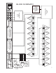
8X192 FIRMWARE EPROM USER REPLACEABLE DIOCARD2 HEADER JUMPERS TO RIGHT=FIXED -15dB GAIN JUMPERS TO LEFT= VARIABLE TRIMPOTS DAC#8 DAC#7 DAC#6 DAC#5 DAC#4 DAC#3 DAC#2 DAC#1 DAC GAIN ADJUSTMENT JUMPERS AND TRIMPOTS JUMPERS SET EITHER FIXED +4dB=-15dBFS OR ENABLE 10 TURN TRIMPOTS FOR MANUAL GAIN ADJUSTMENT DIOCARD1 HEADER ADC#2 JUMPERS TOWARDS BACK=FIXED -15dB GAIN JUMPERS TOWARDS FRONT= VARIABLE TRIMPOTS ADC#7 ADC#8 ADC#5 ADC#6 ADC#3 ADC#4 ADC#1 ADC GAIN ADJUSTMENT JUMPERS AND TRIMPOTS JUMPERS SET EIT
SETTING CLOCKING AND SIGNAL SOURCES 1. NORMAL OPERATION. AD AND DA ON INTERNAL CLOCK. AD FEEDING THE RECORDER, DA MONITORING RECORDER LED ON LED OFF In this mode both the AD and DA run on the internal clock. This mode provides the lowest jitter and most sonically robust performance. External recorders (such as DAW etc) have to be synchronized either to the AD digital outputs (any format: AES or DIOCARD1 or DIOCARD2) or to the converter Worclock output. This example shows 44.
3. NORMAL OPERATION. AD AND DA ON EXTERNAL WORDCLOCK. AD FEEDING THE RECORDER, DA MONITORING RECORDER LED ON LED OFF In this mode both the AD and DA run on an external clock. Holding the "Ext. Clock Source" button selects this mode. Although this mode does not provide the lowest jitter performance it might be desirable for systemic reasons.
5. NORMAL OPERATION. AD AND DA ON EXTERNAL CLOCK OTHER THAN WCK. AD FEEDING THE RECORDER, DA MONITORING RECORDER LED ON LED OFF In this mode both the AD and DA run on an external clock. Although this mode does not provides the lowest jitter performance it might be desirable for systemic reasons. For example a second 8X192 unit running can be coupled with a master 8X192 unit via Firewire cable only. In this case the clock for the second unit is provided via a Firewire card (DIOCARD1 in this example).
7. FORMAT CONVERSION OPERATION. ADC IS OFF, DIGITAL IN TO DIGITAL OUT, DA MONITORING DIGITAL IN. LED ON LED OFF In this mode the 8X192 unit can be used for format conversion between all installed digital interfaces. Once a digital input is selected for "SOURCE TO DIGITAL", the "SAMPLE RATE" switch is disabled and EXT.CLOCK SOURCE and SOURCE TO ANALOG OUT automatically set to selected digital input.
Specifications ADC* Conversion: Linear, 1 Bit * 128x oversampling at 44.1-48kHz 64x oversampling at 88.2-192kHz, optional 64xDSD and 128xDSD Resolution: 24 bit, ( or 1 bit DSD) Sample rates: 44.1kHz, 48kHz, 88.2kHz, 96kHz, 176.4kHz, 192kHz or wordclock 25-200kHz Dynamic Range: 120dB A-weighted, 117dB Total THD+Noise: -106dB (<0.