9000 Series Industrial Gigabit Ethernet Switch User Manual & Installation Guide (Revised 2010-7-2) page 1 of 145
Industrial Gigabit Ethernet Switch Installation Guide ................................................................................................. 7 Safety Warnings ........................................................................................................................................................... 8 INSTALLATION ....................................................................................................................................................... 10 SERVICING ......
Help – Event Log .................................................................................................................................................................... 87 Help – Firmware/Config ......................................................................................................................................................... 88 Help – Logical View ...............................................................................................................................
Get admin status of the port .................................................................................................................................................. 108 Set admin status of a port ...................................................................................................................................................... 108 Show port statistics .................................................................................................................................
Add Multicast MAC Address ................................................................................................................................................ 123 Delete Multicast MAC Address ............................................................................................................................................ 123 Add a Unicast MAC Address .........................................................................................................................................
Set RSTP Port Priority .......................................................................................................................................................... 138 Get RSTP Port Priority.......................................................................................................................................................... 138 Broadcast Packet Count Limit Commands ..............................................................................................................
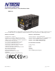
Industrial Gigabit Ethernet Switch Installation Guide 9000 Series The N-TRON 9000 Series Gigabit Ethernet Capable Industrial Ethernet Switch offers outstanding performance and ease of use. It is ideally suited for connecting Ethernet enabled industrial and or security equipment and is a fully managed switch. PRODUCT FEATURES MODULE / SLOT OPTIONS • Full IEEE 802.
Copyright, © N-Tron Corp., 2008-2010 820 S. University Blvd., Suite 4E Mobile, AL 36609 USA All rights reserved. Reproduction, adaptation, or translation without prior written permission from N-Tron Corp. is prohibited, except as allowed under copyright laws. Ethernet is a registered trademark of Xerox Corporation. All other product names, company names, logos or other designations mentioned herein are trademarks of their respective owners.
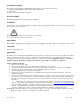
ENVIRONMENTAL SAFETY WARNING: Disconnect the power and allow to cool 5 minutes before touching. ELECTRICAL SAFETY WARNING: Disconnect the power cable before removing any modules, or any enclosure panel. WARNING: Do not operate the unit with the any cover removed. WARNING: Do not work on equipment or cables during periods of lightning activity. WARNING: Do not perform any services on the unit unless qualified to do so. WARNING: Do not block the air vents.
PACKAGE CONTENTS Please make sure the 9000 Series Gigabit Ethernet Switch package contains the following items: 1. 9000 Series Gigabit Ethernet Switch with modules or filler panels 2. Product CD Contact your carrier if any items are damaged. INSTALLATION Read the following warning before beginning the installation: WARNING Never install or work on electrical equipment or cabling during periods of lightning activity. Never connect or disconnect power when hazardous gasses are present.
Replacing a CPU Module: 1. Remove power from the switch. 2. Unscrew the two thumb screws for the CPU module that you are replacing. 3. Using both hands pull on both thumb screws to slide the CPU module out of the 9000BP. 4. Align the new CPU Module such that it slides on the rails and firmly push it into the unit. 5. Screw both thumb screws down till they are finger tight. 6. Reapply the power to the switch. NOTE: All configuration settings are saved to the NVRAM which is stored locally on the CPU Module.
DIN-Rail Mounting Install the unit on a standard 35mm Din-Rail. Recess the unit to allow at least 5” of horizontal clearance for fiber cable bend radius. To mount the unit to the 35mm din-rail, place top edge of the bracket on the back of the unit against the din-rail at a 45° upward angle. Lower the bottom of the unit until it snaps into place.
Panel Mount Mounting Install the unit directly on a wall or sturdy panel such as a bulkhead. Recess the unit to allow at least 5” of horizontal clearance for fiber cable bend radius. To bulkhead mount the unit, place top edge of the bracket on the back of the unit against two screws at a 45° upward angle. Lower the bottom of the unit until it is flush with the wall, and secure the bottom of the unit with two more screws.
FRONT PANEL From Top to Bottom: Gigabit Ports Fiber Ports RJ45 Ports 1000 Base-SX Connections 100 Base-FX Connections Auto sensing 10/100 Base-TX Connections Green LED lights when Power is supplied to the module NOTE: The RJ45 data port has two LED‟s located at the side of the connector. The bottom LED indicates LINK status, and the top LED indicates ACTIVITY.
APPLYING POWER (Side View) Unscrew & Remove the DC Voltage Input Plug from the Power Input Header Install the DC Power Cables into the Plug (observing polarity). Plug the Voltage Input Plug back into the Power Input Header. Tightening torque for the terminal block power plug is 0.5 Nm/0.368 Pound Foot. Verify the Power LED stays ON (GREEN). Note: Only 1 power supply must be connected to power for minimal operation.
N-TRON SWITCH GROUNDING TECHNIQUES The grounding philosophy of any control system is an integral part of the design. N-Tron switches are designed to be grounded, but the user has been given the flexibility to float the switch when required. The best noise immunity and emissions (i.e. CE) are obtained when the N-Tron switch chassis is connected to earth ground via a drain wire. Some N-Tron switches have metal din-rail brackets that can ground the switch if the din-rail is grounded.
CAT5 CABLE SPECIFICATIONS Please reference the illustration below for your Cat5 cable specifications: (Revised 2010-7-2) page 17 of 145
CONNECTING THE UNIT For FX/FXE units, remove the dust cap from the fiber optic connectors and connect the fiber optic cables. The TX port on the FX/FXE models should be connected to the RX port of the far end station. The RX port on the FX/FXE versions should be connected to the TX port of the far end station. For 10/100 Base-TX ports, plug a Category 5E twisted pair cable into the RJ45 connector. Connect the other end to the far end station.
Serial Cable Connect the serial COM port of your PC and the 9000 Series Switch using a standard straight through cable. You will require a cable with a 9-pin or 25-pin sub-D female connector for the PC end, and a 9-pin male sub-D connector for the 9000 Series end.
Overview of Advanced Features Mode of Operation Each port on the switch can be configured into different modes of operation as shown below: Copper Ports: 100Base Fiber Ports: 1000Base Fiber Ports: - Half Duplex - Full Duplex - Full Duplex - Full Duplex - Auto Negotiation Half Duplex In half duplex mode, the CSMA/CD media access method is the means by which two or more stations share a common transmission medium.
Virtual LAN The switch provides support for setting up both tagged Virtual LANs and port based Virtual LANs. A port may belong to any number of Virtual LANs. The VLAN membership of a station is determined by the VLAN(s) that have been defined for the port to which the station is connected. If a station should move from one port to another, it loses its current VLAN membership and inherits that of the new port it is connected to.
IGMP Snooping IGMP Snooping is enabled by default, and the switch is Plug and Play for IGMP. IGMP snooping provides intelligent network support for multicast applications. In particular, unneeded traffic is reduced. IGMP Snooping is configured via the console and if enabled, then operates dynamically upon each power up. Also, there can be manual only or manual and dynamic operation. Note that “static multicast group address” can be used whether IGMP Snooping is enabled or not.
TROUBLESHOOTING 1. Make sure the (Power LED) is ON. 2. Make sure you are supplying sufficient current for the version chosen. Note: The Inrush current will exceed the steady state current by ~ 2X. 3. Verify that Link LED‟s are ON for connected ports. 4. Verify cabling used between stations. 5. Verify that cabling is Category 5E or greater for 100Mbit Operation. SUPPORT Contact N-Tron Corp. at: TEL: 251-342-2164 FAX: 251-342-6353 www.n-tron.
Web Software Configuration Web Management Enter the switch‟s IP address in any web browser and login to the web management feature of the 9000 Series.
Web Management - Home When the administrator first logs onto a 9000 Series switch the default home page will be displayed. On the left hand side of the screen there is a list of configurable settings that the 9000 Series switch will support. This section of the manual will go through each and every choice listed on the left hand side of the screen and explain how to configure those settings.
Web Management – Menu Structure To the left, there is a menu which is shown fully opened below. The pages opened by each of the individual selections are described in the rest of this section. The use of each of these pages is also described in this section. In most of the descriptions, only the right side of the page is shown.
Administration – System The System tab under the Administration category lists the following information about the switch: IP Address Subnet Mask Default Gateway MAC Address System Up Time Name Contact Information Location By selecting the modify button you will be able to change the switch‟s IP Address, Subnet Mask, Default Gateway, Name, Contact information, and the Location of the switch through the web management features.
Administration – SNMP The SNMP tab under the administration category shows a list of IP Addresses that act as SNMP Traps. The Get, Set, and Trap Community Names are also shown here. By selecting the modify button you will be able to change any of the fields listed. This allows the user to set an IP address for an SNMP Trap or change the Community Names. Systems that are listed as an SNMP Trap will be sent basic networking changes made to the switch such as ports going down or being linked.
Administration – Slots The Slots tab under the administration category allows users to change the configuration of the slots that are populated in the 9000 Back Plane. The switch may not operate correctly if the slots are not configured properly. You must click Update if you wish to keep the changes. Following the Update button, the user may be prompted to Save and Restart the switch in order for changes to take effect.
Ports – Configuration The Configuration tab under the Ports category will show a detailed overview of all the active ports on the switch.
(Revised 2010-7-2) page 31 of 145
Ports – Configuration, Continued… The User can click on the Port Number to configure each port individually.
Ports – Security The Security tab under the Ports category will show a list of all the active ports and the security Lock State for each port. Administrators can change the Port Security by a per port basis. If the Port is enabled through this the port will be locked and will only allow known MAC addresses to communicate through the port. Unknown MAC addresses will be logged in the Intrusion Log.
Ports – Intrusion Log The Intrusion Log tab under the Ports category will show a list of intruders along with their MAC addresses. The log will show what Port the intruder attempted to access your network on and log the system time when it occurred. The log can be easily cleared.
Ports – Mirroring A mirroring port is a dedicated port that is configured to receive the copies of Ethernet frames that are being transmitted out and also being received in from any other port that is being monitored. The Mirroring tab under the Ports category displays the status including the list of Source Ports and the Destination Port that the Sources are being mirrored to.
Ports – Trunking The Trunking tab under the Ports category displays a list of trunks configured on the switch and the following details regarding each trunk: Trunk ID Trunk Name Trunk Ports Trunk State By selecting the Create button, you can add a trunk group. NOTE: RSTP must be disabled in order to use the Trunking Feature. N-Ring Managers cannot have trunking enabled. A maximum of 4 ports of the same speed can constitute a valid trunk. Only 1 Trunk per switch can be created.
Ports – Trunking, Continued… Once the Trunk Group is created you will see detailed information for that trunk group, but it should have a disabled state by default. In order to enable the Trunk Group you need to click on the State Button above. The following page should load asking for the Trunk ID and what the Trunk State is. NOTE: RSTP must be disabled in order to use the Trunking Feature. N-Ring Managers cannot have trunking enabled. A maximum of 4 ports of the same speed can constitute a valid trunk.
Statistics – Port Statistics The Ports Statistics tab under the Statistics category displays a list of MIB Parameters. Each port has a separate counter for each parameter. This gives users the ability to see what kind of packets are going over which ports. At the bottom of each page for each port there are two buttons. Refresh will update the statistics for that port number and Clear will reset all the counters for that port number.
Statistics – Ports Utilization The Ports Utilization tab under the Statistics category shows all the ports on the switch and will display a bar graph showing the percentage of bandwidth being used. These figures and bars are for a general feeling of what the bandwidth usage is. N-Tron recommends the use of N-View in order to get a precise bandwidth usage figure.
VLAN – Ingress Filter The Ingress Filter tab under the VLAN category shows all the ports on the switch and if the Ingress Filter Rule is enabled or disabled for each port. To change the Ingress Filter Rule simply click on the Modify button on the page above, select the port number from the pull-down menu that you wish to modify and then choose to either enable or disable the Ingress Filter Rule.
VLAN – Port Based The Port Based tab under the VLAN category shows all the VLANs that are configured on the switch and details about the VLANs such as port numbers and tagged VLAN settings. To add a VLAN simply click on the Add button on the page above and fill in the desired fields. The example below would set up a basic port based VLAN for ports A1-A6.
VLAN – Port Based, Continued… Now the page will display the new VLAN and moved ports A1-A6 from the default VLAN down to vlan2 that was just created. To delete or remove VLANs that are no longer wanted simply click on the Delete button on the main Port Based VLAN page. That button will load the page where the user can enter the VLAN ID that he or she wishes to delete.
VLAN – Port Based, Continued… Once the VLAN is deleted it will no longer appear on the main page and all the ports are now back under the default VLAN. When a port based VLAN is created the PVID (Port VLAN ID) will change automatically to be members of the new VLAN they are a part of. If you delete this VLAN the PVIDs will not automatically return to the default VLAN. Users should keep this in mind when removing VLANs, and may need to manual change the PVIDs for any affected ports.
Bridging – Aging Time The Aging Time tab under the Bridging category will display the currently configured Aging Time. This page allows users to modify this variable to meet their needs. After selecting the Modify button the user will be presented with a page that allows the number to be entered into and updated. The default aging time is 20 seconds.
Bridging – Unicast Addresses The Unicast Addresses tab under the Bridging category will display a list of MAC addresses that are associated with each respective port number. This can be used to statically assign a MAC address access to a single port on the switch. Following the Add button on the page above, the administrator must enter a valid MAC address and associate it with a port number on the switch. Once the administrator hits the Update button the changes will take effect instantly.
Bridging – Unicast Addresses, Continued… Following the Delete button on the page above, an administrator can select a static MAC address from the list using a pull-down menu. After selecting the MAC address the administrator needs to press the Delete button on this page to remove the entry .
Bridging – Multicast Addresses The Multicast Addresses tab under the Bridging category will display a list of Multicast Group Addresses that are associated with respective port numbers. This may be used to statically assign a Multicast Group Address access to a group of ports on the switch. These are egress filters. Following the Add button on the page above, the administrator must enter a valid Multicast Group Address and associate it with a port number or list on the switch.
Bridging – Multicast Addresses, Continued… After adding a Multicast Group Address it will appear on the main list and will show the associated ports that go along with that address. Following the Delete button on the page above, the administrator will be presented with a list of Multicast Group Addresses that are configured on the switch. Using the pull-down menu the administrator should select the desired port to be removed. Then click on the Delete button at the bottom of the page.
RSTP – RSTP Configuration The RSTP Configuration tab under the RSTP category will display the RSTP information for the first VLAN. Using the pull-down menu at the top of the page an administrator can choose which VLAN to configure RSTP on. Once the VLAN is selected the administrator may configure the bridge by clicking on the Configuration button in the middle of the page. The configuration screen for the VLAN that was previously selected will look like the example below.
RSTP – RSTP Configuration, Continued… It is valid to have RSTP rings linked to non-N-Ring ports of active N-Ring Members, as above. As marked above, it is not valid to expect RSTP to block redundant N-Ring links nor for N-Ring to block redundant RSTP links.
RSTP – RSTP Configuration, Continued… Following the link for the view RSTP Port Configuration at VLAN# the administrator or user can see the current RSTP status of the ports on that VLAN. This will show information such as the Path Cost and the Port State. If the switch sees a redundant path it will put the port with the highest Path Cost into Blocking mode where it will discard packets coming in on that port.
RSTP – RSTP Configuration, Continued… If the administrator selects one of the ports on the previous screen he or she can change the Port‟s Path Cost, Port‟s Priority and the status of Admin Edge and Auto Edge.
IGMP – Configuration The Configuration tab under the IGMP category will display the IGMP basic configuration settings. By default IGMP is enabled. Following the Modify button on the previous page, the administrator will see a list of configurable fields for the IGMP configuration. Once these fields are filled in to meet the needs of the administrator‟s network the changes may be saved by clicking the Update button at the bottom of the page.
IGMP – Show Group and Show Router The Show Group tab under the IGMP category will display a list of IGMP groups based on the Group IP and the port number that it is associated with. The Show Router tab under the IGMP category will display a list of Auto-detected Router IPs and the port numbers that they are associated with.
IGMP – RFilter The „rfilter‟ (Router Multicast Data Filter) function allows you to choose whether or not DATA frames with KNOWN group multicast addresses are sent to the „router‟ ports (links to other switches). Control packets (Join, Leave) will be sent to the router(s) regardless of this setting. “KNOWN” is known from dynamic IGMP Snooping operations.
Modifying rfilter port settings: (Revised 2010-7-2) page 56 of 145
N-Ring – Configuration The Configuration tab under the N-Ring category will display the N-Ring basic configuration settings. By default N-Ring is in AutoMember mode and the N-Ring Agingtime is 20 seconds. Following the Modify button, the administrator will see a list of configurable fields for the N-Ring configuration, as below. The N-Ring Agingtime has a default of 20 seconds and is separate from the Bridging Aging Time.
N-Ring Configuration (continued) The “N-Ring Mode” is one of three, as below: If N-Ring Mode is “Manager”, then a pull-down allows selection as available of ports A1 and A2, or E1 and E2 as N-Ring ports.
N-Ring Configuration (continued) If N-Ring Mode is “Manager”, then a pull-down allows selection of displaying N-Ring Summary Status on all web pages or on N-Ring pages only: (Revised 2010-7-2) page 59 of 145
N-Ring Configuration (continued) If N-Ring Mode is “Manager”, then VLAN ID can be set to a unique vlan id (1 ~ 4094). Default is 3333. If N-Ring Mode is “Manager”, then a pull-down allows selection as to whether the N-Ring ports are members of the VLANs Tagged or Untagged ports. Default is Tagged. Once these fields are filled in to meet the needs of the administrator‟s network the changes may be saved by clicking the Update button at the bottom of the page. NOTES: 1.
N-Ring – Status The Status tab under the N-Ring category will display the N-Ring status.
Below is an example of N-Ring Status from an N-Ring Manager with a healthy N-Ring: N-Ring OK N-Ring Status View Switch is an N-Ring Manager, using N-Ring Aging Time = 20 Seconds Refresh every 6 secs. Update Pause Print... 12 Active Members Detected In Current N-Ring (12 reporting) Switch No MAC Address (Revised 2010-7-2) IP Address Subnet Mask Name Ports RM 00:07:af:ff:e4:a0 192.168.1.227 255.255.255.0 N-TRON Switch A2 A1 1 00:07:af:ff:ef:60 192.168.1.224 255.255.255.
Below is an example of N-Ring Status from an N-Ring Manager with a faulted N-Ring. The red fields on the N-Ring Map show problems. Ports that are red indicate that the port is not linked. MAC addresses that are red indicate that there is no communication to that switch. The red “Ring Broken” line shows where the N-Ring is broken. N-Ring Fault N-Ring Status View Switch is an N-Ring Manager, using N-Ring Aging Time = 20 Seconds Refresh every 6 secs. Update Pause Print...
In rare cases an N-Ring can have a “Partial Fault”. An example of this is to have a break in just one fiber in a duplex channel fiber pair. The screenshot below shows N-Ring Manager Status when a „Higher‟ N-Ring Port (A2 or E2) is not receiving self health frames all the way around the N-Ring, though the other (low A1/E1) N-Ring port is: N-Ring Partial Fault (A2 is not receiving self health from A1) N-Ring Status View Switch is an N-Ring Manager, using N-Ring Aging Time = 20 seconds Refresh every 6 secs.
NView – Configuration The Configuration tab under the NView category will display two basic variables for NView, the status and the interval between packets. Following the Modify button on the above example, the administrator can modify the variable to change the frequency with which NView reports information. Increasing the interval will slow the update rate. Decreasing the interval will allow NView to report more frequently. Additionally, you may Disable or Enable NView altogether.
NView – Ports The Ports tab under the NView category will display a list of all the configured ports on the 9000 unit along with the ports transmitting multicast packets and MIB stats respectively.
NView – Ports, Continued… Following the Modify button on the previous example, the administrator can modify these two variables to enable or disable multicast out of the port and if MIB stats are sent out for those ports.
EventLog – Log Statistics The Log Statistics tab under the EventLog category will show a list of how many times a type of event took place. On the bottom of the page it should also list the maximum log size which can be modified. There are 5 types of events that the 9000 will categorize messages in. If the log level is set to 1, the 9000 will log all 5 types of events. If the log level is set to 5 it will only record the Critical types (the 5 th level).
EventLog – Show Events The Show Events tab under the EventLog category will show a list of events that have occurred in the order in which they occurred. There is a time stamp for each event and they are categorized by the severity of the event.
Firmware/Config – TFTP The TFTP tab under the Firmware/Config category gives the administrator the ability to upload or download a config file for a 9000 Series switch. This gives administrators the ability to backup their configurations to a server offsite in case they need to reload their custom configurations at a later time.
Firmware/Config – FTP The FTP tab under the Firmware/Config category gives the administrator the ability to upload or download a config file for a 9000 Series switch. This gives administrators the ability to backup their configurations to a server offsite in case they need to reload their custom configurations at a later time.
Support – Web Site and E-mail If at any point in time you get confused or would like additional support directly from N-Tron, you may visit N-Tron‟s web site, or e-mail N-Tron directory with the links provided for more information.
BPCL – Broadcast Packet Count Limit Configuration The BPCL link will display all the ports that are installed in the 9000 Series unit and will list the BPCL Percentage for each port. These are egress filters. A modify button is provided to change these fields. Following the Modify button on the previous example, the administrator can modify the BPCL Percentage for each port. The default BPCL is 3% for all ports.
User Mgmt – Adding Users The User Management link will display a list of all the users who have access to the management features of the switch and their access permissions. Following the Add button on the previous example, the administrator can add another user and assign the user a username, a password, and the user‟s permissions (user/administrator). A page should display after the administrator clicks the Add button stating that the user was successfully added.
User Mgmt – Removing Users In order to remove a user, simply click on the Remove button at the bottom of the page. Following the Remove button on the last page, the administrator can remove a user by entering in the user‟s name and clicking the Remove button. A page should follow stating that the user was successfully removed from the list.
Logical View The 9000 Web Management offers a logical view of the switch. Here a user or administrator can see a graphical depiction of the 9000 switch with the installed modules that have been configured in it. Ports that are linked will turn green, while ports that are not linked will show up as black. The example below shows only port 4 on the 9006TX module is linked. The other ports are currently in the down state (not being used).
Configuration – Save or Reset The Configuration section of the web management gives an administrator the ability to save a running configuration into the NVRAM. This step is needed in order for the switch to remember any changes after a power cycle. The Reset Configuration button will reload N-Tron‟s factory default configuration settings. Doing so will re-configure the 9000 Series switch to factory defaults.
Help – Overview When the Help link is clicked on, you will see the Overview page that will have some basic definitions and more specific choices at the top of the screen. Although this page is not as detailed as the manual is, it gives you a basic feel for different features the 9000 offers.
Help – Administration Selecting the Administration link on the help page, the administrator or user can see some information regarding the configuration options in the Administration category on the left side of the web management.
Help – Ports Following the Ports link on the help page, the administrator or user can see some information regarding the configuration options in the Ports category on the left side of the web management.
Help – Statistics Following the Statistics link on the help page, the administrator or user can see some information regarding the configuration options in the Statistics category on the left side of the web management.
Help – VLAN Using the VLAN link on the help page, the administrator or user can see some information regarding the configuration options in the VLAN category on the left side of the web management.
Help – BPCL Using the BPCL the link on the help page, the administrator or user can see some information regarding the configuration options in the BPCL category on the left side of the web management.
Help – IGMP Following the IGMP link on the help page, the administrator or user can see some information regarding the configuration options in the IGMP category on the left side of the web management.
Help – Bridging Using the Bridging link on the help page, the administrator or user can see some information regarding the configuration options in the Bridging category on the left side of the web management.
Help – RSTP Using the RSTP link on the help page, the administrator or user can see some information regarding the configuration options in the RSTP category on the left side of the web management.
Help – Event Log Using the Event Log link on the help page, the administrator or user can see some information regarding the configuration options in the Event Log category on the left side of the web management.
Help – Firmware/Config Using the Firmware/Config link on the help page, the administrator or user can see some information regarding the configuration options in the Firmware/Config category on the left side of the web management.
Help – Logical View Using the Logical View link on the help page, the administrator or user can see some information regarding the configuration options in the Logical View category on the left side of the web management.
Help – User Mgmt Using the User Mgmt link on the help page, the administrator or user can see some information regarding the configuration options in the User Mgmt category on the left side of the web management.
Help – N-View Using the N-View link on the help page, the administrator or user can see some information regarding the configuration options in the NView category on the left side of the web management.
Help – N-Ring Using the N-Ring link on the help page, the administrator or user can see some information regarding the configuration options in the N-Ring category on the left side of the web management.
Help – Others Following the Others link on the help page, the administrator or user can see some information regarding other links or categories on the left hand side of the web manager, as above.
CLI Commands Clear Command Name Description Syntax Parameters Examples clear Clears the screen. The cleared screen shows only the command-line prompt and the cursor. clear None N-TRON/Admin#[1]> clear The entire screen will be cleared… … … … … N-TRON/Admin#[2]> NOTES “?” (HELP) Command Name Description “?” Without , this command will list all the available commands. This is the same as the default behavior of the help command.
Top Command Name Description Syntax Parameters Examples top Changes the context to the topmost (global) level. If already at the topmost context, the command is simply ignored top None N-TRON/Admin#[1]system> show N-TRON/Admin#[2]system/show> top N-TRON/Admin#[3]> top N-TRON/Admin#[4]> NOTES Up Command Name Description Syntax Parameters Examples up Changes the context to the next higher level.
“!” Command Name Description Syntax Parameters Examples ! Repeats the command in the history list identified by . !! – repeats the last command executed. ! – repeats the command in the history list associated with reference number . ! – repeats the most recent command that begins with the string . Any non-whitespace characters that follow are appended to the referenced command prior to its execution.
“$” Command Name Description Syntax Parameters $ This command copies the command identified by reference number from the history list into the next command line allowing the user to edit the command for corrections or changes. $ n The reference number of the command in the history list that has to be edited. Examples N-TRON/Admin#[1]> whoaim As shown above the command whoaim was entered instead of whoami. To edit the already entered command do as follows.
System Configuration Commands Set Mode IP config Command Name Description Syntax Parameters Example NOTES system set modeipconfig To set the IP address mode of the system system set modeipconfig manual Uses a static IP address scheme (default mode) dhcp Pulls an IP address from a DHCP server on the LAN bootp Pulls an IP address from a Bootp server on boot up N-TRON/Admin#[1]> system set modeipconfig dhcp Bootp is an older version of DHCP, DHCP is recommended for a dynamic address sche
Get Gateway Address of the System Command Name system get gateway Description To display the gateway address of the system Syntax system get gateway Parameters None N-TRON/Admin#[4]> system get gateway Example System Gateway Address : 192.168.1.
Set System Location Command Name Description Syntax Parameters system set syslocation To set the location details of the system system set syslocation Location-of-the-system The details of where the system is located Example N-TRON/Admin#[1]> system set syslocation “San Jose” N-TRON/Admin#[2]> system set syslocation Hyderabad Notes Please ensure to use “ “ for supplying arguments with spaces Get System Uptime Command Name Description Syntax Parameters Example system get sysup
Set SNMP Set Community name Command Name system set snmpsetcommunity Description To set the community name for performing snmpset operation Syntax system set snmpsetcommunity Parameters Community-Name The name of the community to be used for performing snmpset operation N-TRON/Admin#[1]> system set snmpsetcommunity private Example N-TRON/Admin#[1]> system set snmpsetcommunity “NTron_Systems” Notes Arguments cannot have spaces. You can use an underscore („_‟) instead of a space.
Show all configuration parameters related to SNMP manager Command Name system show snmpinfo Description To show all the configuration parameters related to snmp manager Syntax system show snmpinfo Parameters None Example N-TRON/Admin#[33]system/show> snmpinfo System SNMP Configuration : IP Address - Trap Station#1 IP Address - Trap Station#2 IP Address - Trap Station#3 IP Address - Trap Station#4 IP Address - Trap Station#5 SNMP Get Community Name SNMP Set Community Name SNMP Trap Community Name : : : : :
User Management Commands Show System Users Command Name Description Syntax Parameters Example system show users Shows a list of users and their permissions on the system system show users None N-TRON/Admin#[1]> system show users Serial -----1 2 Username -------admin ntron Access Permissions -----------------admin user NOTES Add a System User Command Name Description Syntax Parameters system add user To add a user to the system system add user [access permission] Username A string of at least
Remove a System User Command Name Description Syntax Parameters system remove user To remove a user from the users list system remove user username The user‟s username that is to be removed Example N-TRON/Admin#[1]> system remove user ntron Do you really want to delete the above user: User successfully deleted Notes Only users with admin permissions can operate this command.
Image Loader Commands Download Image through COM port Command Name image download Description To download new firmware image through the serial port on the switch. Syntax image download Parameters None N-TRON/Admin#[1]> image download Examples NOTES Uses XModem protocol when transferring the file. N-Tron recommends that you use TFTP or FTP when updating the firmware. TFTP and FTP are both much faster.
FTP Commands Set Username Command Name Description Syntax Parameters Example ftp set username To set the user name which will be used to log into the FTP server ftp set username Username The user name for logging on to the FTP server eg.1 N-TRON/Admin#[1]> ftp set username ntron eg.2 N-TRON/Admin#[1]> ftp set username admin Notes Set Password Command Name Description Syntax Parameters The user name should be a valid one; else logging into FTP server will fail.
Display FTP related configuration parameters Command Name ftp show Description To display the present value of all the FTP related configuration parameters Syntax ftp show Parameters None N-TRON/Admin#[1]> ftp show Example Notes Perform the configuration file transfer action Command Name ftp config Description To perform the desired File Transfer action (either get or put).
Port Manager Commands Get the link state of a given port Command Name port get linkstate Description This command is used to get the present link state of a given port. Whenever there is an active connection, link state (operational state) is up; else link state is down. Syntax port get linkstate Parameters port-no Port number. (1 ~ 26).
Show port statistics Command Name Description Syntax Parameters Examples NOTES port show stats This command is used to get the port statistics of a given port for all available counters. port show stats port-no Port number. (1 ~ 26).
Syntax Parameters given port number . port get duplexmode port-no Port number. (1 ~ 26) Examples N-TRON/Admin#[1]> port get duplexmode 4 Duplex mode of [4] port is: [half] N-TRON/Admin#[2]> port get duplexmode 23 Duplex mode of [23] port is: [full] NOTES Check whether port-no is in the valid range. (1 ~ 26) Set the port duplex mode Command Name Description Syntax Parameters port set duplexmode Sets the port duplex mode (HALF_DUPLEX / FULL_DUPLEX) for a given port number.
Port number (1 ~ 24). Examples N-TRON/Admin#[1]> port get Auto negotiation mode is : N-TRON/Admin#[2]> port get Auto negotiation mode is : NOTES Check whether port-no is in the valid range. (1 ~ 24) Set Auto-negotiation State Command Name Description Syntax Parameters autonego 6 [enabled] autonego 24 [disabled] port set autonego Sets the auto negotiation mode of a given port to either enable or disable.
pvid-number The VLAN-ID number of the VLAN that this port will be a member of Examples NOTES Set Backpressure Command Name Description Syntax Parameters Examples NOTES Set Intruderstate Command Name Description Syntax Parameters Examples NOTES Set Priority Level Command Name Description Syntax Parameters Examples NOTES Show Configuration Command Name Description Syntax Parameters Examples NOTES Show Intruders Command Name Description Syntax Parameters Examples NOTES (Revised 2010-7-2) N-TRON/Admin#[1]>
Show Link Utilization Command Name Description Syntax Parameters Examples NOTES Get Flow Control Command Name Description Syntax Parameters Examples NOTES Get Name Command Name Description Syntax Parameters Examples NOTES Get State Of Priority Command Name Description Syntax Parameters port show linkutilization Shows the utilization statistics for all the ports including %bandwidth, %in, %out, RX bytes, and TX bytes for each port.
Get STP Status Command Name Description Syntax Parameters port get STP Status Displays the Spanning Tree Protocol Status on a given port.
Trunk related commands Enable or Disable Trunking Command Name Description Syntax Parameters Examples NOTES Modify Trunk Command Name Description Syntax Parameters Examples NOTES Create Trunk Command Name Description Syntax Parameters Examples NOTES (Revised 2010-7-2) trunk set To enable or disable the trunk that is already created. trunk set enable trunk set disable N-TRON/Admin#[1]> trunk set enable Trunking is activated.
Delete Trunk Command Name Description Syntax Parameters Examples trunk delete To delete the trunk . trunk delete N-TRON/Admin#[1]> trunk delete Trunk has been deleted. NOTES Show Trunk Information Command Name Description Syntax Parameters Examples trunk show To show all the trunks information.
Mirroring related commands Set Mirror config Command Name Description Syntax Parameters Examples NOTES mirror set config To the mirroring feature of the switch, for specified ports. mirror set config dest-port Destination port is the snooper port onto which the selected source ports traffic is to be mirrored. The gigabit ports cannot be destination ports. src-ports List of ports to be monitored.
VLAN Related Commands Add VLAN Entry Command Name Description Syntax Parameters vlan add To create a Port based Virtual LAN vlan add -untagged | -tagged [-name ] [-admit ] [-mirror ] vlan-id Unique vlan id (2 ~ 4094). mgmt port Either 1 or 0. „1‟ sets this vlan as a management vlan. vlan name Unique vlan name, which can be used to identify the group.
Modify an existing VLAN Command Name Description Syntax Parameters Examples vlan modify Modifies an existing VLAN. vlan modify -untagged | -tagged [-name ] [-admit ] [-mirror ] vlan-id unique vlan id ( 2 ~ 4094). mgmt port Management Port, yes or no (1 or 0). -untagged port mask List of ports that are to be included under this VLAN.
Set VLAN to defaults Command Name Description Syntax Parameters Examples NOTES Set VLAN Ingress Filter Command Name Description vlan set default Removes all the configured vlans and add all the ports under the Default vlan. vlan set default None N-TRON/Admin#[1]> vlan set default Changing anything on a VLAN will turn on RSTP on all VLANs as a precautionary measure.
Eventlog Related Commands Get Eventlog count Command Name Description Syntax Parameters Examples eventlog get count To display the logged events count eventlog get count None N-TRON/Admin#[1]> eventlog get count No.
Show Eventlog events Command Name Description Syntax Parameters Examples NOTES (Revised 2010-7-2) eventlog show events To display the logged events eventlog show events None N-TRON/Admin#[1]> eventlog show events page 122 of 145
Bridging Related Commands Add Multicast MAC Address Command Name Description Syntax Parameters Examples NOTES Delete Multicast MAC Address Command Name Description Syntax Parameters Examples NOTES Add a Unicast MAC Address Command Name Description Syntax bridge add multicastmac Adds a multicast mac address which is associated with a vlan.
Display List of Configured Static MAC Addresses Command Name bridge show staticmac Description To view the list of configure static mac addresses Syntax bridge show staticmac Parameters which set of static mac addresses to show N-TRON/Admin#[1]> bridge show staticmac all Examples N-TRON/Admin#[2]> bridge show staticmac multicast N-TRON/Admin#[3]> bridge show staticmac unicast NOTES Set Aging Time Command Name Description Syntax Parameters Examples NOTES Disp
Display Mac count Command Name Description Syntax Parameters Examples NOTES (Revised 2010-7-2) bridge show maccount Displays the total count of the static mac addresses.
IGMP Related Commands Enable IGMP Command Name Description Syntax Parameters Examples igmp set enable The igmp status is made to enable igmp set enable None NOTES The status can be viewed through the igmp show config command Disable IGMP Command Name Description Syntax Parameters Examples igmp set disable The igmp status is made to disable igmp set disable None N-TRON/Admin#[1]> igmp set enable igmp status is Enabled N-TRON/Admin#[2]> igmp show config Igmp : Enabled Query Mode : auto Router Mode : aut
Show IGMP router Command Name Description Syntax Parameters Examples NOTES Set IGMP query mode Command Name Description Syntax Parameters Examples NOTES Set IGMP router port Command Name Description Syntax Parameters Examples NOTES Set IGMP router mode Command Name Description Syntax Parameters Examples NOTES (Revised 2010-7-2) igmp show router The igmp show router command is used to display the auto-detected routers at present.
Show IGMP rfilter mode Command Name Description Syntax Parameters Examples igmp show rfilter The igmp show rfilter command is used to display the rfilter status by port(s). Usage: igmp show rfilter port-list|all Enter a specific port number list or specify all ports N-TRON/Admin#[22]> igmp show rfilter all N-TRON/Admin#[22]igmp/show> igmp show rfilter 5 Port No. IGMP RFilter ---------------------------5 DISABLE N-TRON/Admin#[6]igmp/show> igmp show rfilter 5-7 Port No.
N-Ring Related Commands N-Ring get agingtime Command Name Description Syntax Parameters Example n-ring get agingtime To display the N-Ring Agingtime of the device n-ring get agingtime None N-TRON/Admin#[1]> n-ring get agingtime N-Ring Aging Time NOTES N-Ring set agingtime Command Name Description Syntax Parameters Examples NOTES N-Ring get webfault Command Name Description Syntax Parameters Example : 20 Default: 20 seconds and is separate from the Bridging Aging Time.
N-Ring set interval Command Name Description Syntax Parameters Examples n-ring set interval Sets the Self-Health Packet interval and missed threshold. n-ring set interval [missed] interval and missed N-TRON/Admin#[36]n-ring/set> n-ring set interval 1 3 Self Health Packet interval set to 1 Maximum Missed Packets set to 3 NOTES N-Ring get mode Command Name Description Syntax Parameters Example The interval is in 10 millisecond increments.
N-Ring show status Command Name Description Syntax Parameters Examples n-ring show status Shows the current N-Ring status of the switch. If Manager, shows ring members. Shows if Automember or active member. If active (manager or member) shows N-Ring ports.
N-Ring set keepalive Command Name Description Syntax Parameters Examples n-ring set keepalive Set timeout after which an N-Ring member will drop back to RSTP mode on the N-Ring ports after loosing communication with the N-Ring manager.
Configuration Related Commands Save Configuration Command Name Description Syntax Parameters Examples NOTES Load Default Configuration Command Name Description Syntax Parameters Examples config save The configuration will be saved to the flash. config save None N-TRON/Admin#[1]> config save config erase This command is useful to erase the configuration data config erase None N-TRON/Admin#[1]> config erase Load Factory Default Setting.
Rapid Spanning Tree Protocol Related Commands Set RSTP Admin Edge Command Name Description Syntax Parameters Examples rstp set adminedge Sets the Adminedge value of a port in a Vlan. rstp set adminedge vlan id Vlan Id containing the port for which the adminedge is to be set. port no Port number in the Vlan to be set. status Status of the adminedge of the port to be set.
Set RSTP Bridge Admin Status Command Name Description Syntax Parameters Examples rstp set bridgeadminstatus Sets the Bridge Admin Status of the given Vlan-ID. rstp set bridgeadminstatus vlan id Vlan Id for which the priority to be set. bridge adminstatus Status of the Bridge to be set.
Set RSTP Bridge Hello Time Command Name Description Syntax Parameters rstp set bridgehellotime To set the HelloTime for a given Vlan-Id. With STP, Hello Time is the time intervals that the root bridge sends out new BPDUs to the rest of the network. Other STP capable switches will forward these BPDUs along. With RSTP every RSTP capable switch will generate new BPDUs and send them out on every Hello Time Interval.
Set RSTP Bridge Priority Command Name Description Syntax Parameters rstp set bridgepriority Sets the Bridge Priority. The root bridge on the network will be the one with the lowest bridge priority, or the lowest MAC address if the priorities are the same (as per IEEE 802.1D specification). rstp set bridgepriority vlan-id Vlan Id for which the priority to be set. bridge priority Priority of the Bridge to be set. The value should range between 0 and 65535. (as per IEEE 802.
Set RSTP Port Priority Command Name Description Syntax Parameters rstp set portpriority To set the priority of the port for a given port in the given vlan-id. STP and RSTP use the port priority to determine which port to place into forwarding mode when there are 2 or more ports to choose from. rstp set portpriority vlan-id Vlan Id to which the port belongs. port no The portnumber for which the port priority is to be set. port priority The Port priority value to be set.
Broadcast Packet Count Limit Commands Get the Broadcast Packet Count Limit for one port Command Name broadcast get percentage Description Displays the broadcast packet percentage for a particular port. Syntax broadcast get percentage Parameters port-number The port number must range between 1 and the maximum port number in the switch.
VLAN Configuration Examples Example 1 – Basic understanding of port based VLANs VLAN Configuration View Ports Configuration View VLAN Status : Enable Port Port PVID No Name VLAN ID VLAN Name Untagged Port(s) Tagged Port(s) Mgmt Port Admit Mirror Port 1 Default VLAN A3-A6,B1-B6,C1-C6,D1-D6 -YES All 0 2 VLAN -2 A1-A2 -- YES All 0 Receiving Port # Tagged VID in packet Destination Address Transmitting Port #s Notes Port A1 Port A1 Port A1 Port A3 Port A3 Port A3 Untagged Untagged VID 4 Untagged
Example 3 – Basic understanding of tagged VLANs (Admit – All) VLAN Configuration View Ports Configuration View VLAN Status : Enable VLAN ID VLAN Name Untagged Port(s) Tagged Port(s) Mgmt Port Admit Mirror Port 1 Default VLAN -- A3-A6,B1-B6,C1-C6,D1-D6 YES All 0 2 VLAN -2 -- A1-A2 YES All 0 Port Port PVID No Name 1 A1 ** 2 A2 ** 3 A3 ** ...
Example 5 – Basic understanding of Overlapping VLANs VLAN Configuration View Ports Configuration View VLAN Status : Enable VLAN ID VLAN Name Untagged Port(s) Tagged Port(s) Mgmt Port Admit Mirror Port Port Port PVID No Name 1 Default VLAN -- -- YES All 0 2 VLAN -2 A1-A6,B1-B6,C1-C6,D1-D6 -- YES All 0 1 A1 4 3 VLAN -3 A2-A6,B1-B6,C1-C6,D1-D6 -- YES All 0 2 A2 2 4 VLAN -4 A1-A2 -- YES All 0 3 A3 3 ...
KEY SPECIFICATIONS Switch Properties Number of MAC Addresses: Aging Time: Latency Type: Backplane Speed: Switching Method: 4,096 Programmable 2.9 µs 6.6Gb/s Store & Forward Physical Height: Width: Depth: Weight (max): Din-Rail mount: 5.2" (13cm) 9.0" (22.8cm) 5.6" (14.2cm) 5.0 lbs 35mm Electrical Redundant Input Voltage: 10-30 VDC Input Current (max): 2.5 A@24V (fully populated) Inrush @ 24VDC: 16.0 A for 7.
100 Mb Fiber Transceiver Characteristics Fiber Length 2km* 15km** 40km** 80km** TX Power Min -19dBm -15dBm -5dBm -5dBm RX Sensitivity Max -31dBm -31dBm -34dBm -34dBm Wavelength Min/Max * Multimode Fiber Optic Cable ** Singlemode Fiber Optic Cable 1310nm 1310dm 1310dm 1550nm Gigabit Fiber Transceiver Characteristics Fiber Length TX Power Min RX Sensitivity Max Wavelength Assumed Fiber Loss Laser Type 550m* with 50/125 µm 300m* with 62.5/125 µm 10km** 40km** 80km** -9.5dBm -9.
N-TRON Limited Warranty N-TRON, Corp. warrants to the end user that this hardware product will be free from defects in workmanship and materials, under normal use and service, for the applicable warranty period from the date of purchase from N-TRON or its authorized reseller.