
Owner's Manual


1 RS-232: Connect this interface using RS-232 serial cable (not
supplied) to any Windows® compatible PC to allow remote control of
the C 356BEE via compatible external controllers. NAD is a certied
partner of AMX and Crestron and fully supports these external devices.
Check out the NAD website for information about AMX and Crestron
compatibility with NAD. See your NAD audio specialist for more
information.
2 12V TRIGGER OUT: The +12V TRIGGER OUT is used for controlling external
equipment that is equipped with a +12V trigger input. This output will
be 12V when the C 356BEE is ON and 0V when the unit is either OFF or in
standby. This output can drive a load up to 50mA at 12V.
3 IR IN/OUT: These mini-jacks accept and output remote-controlled
codes in electrical format, using industry-standard protocols, for use
with “IR-repeater” and multi-room systems and related technologies.
IR IN: This input is connected to the output of an IR (infrared) repeater
(Xantech or similar) or the IR output of another component to allow
control of the C 356BEE from a remote location.
IR OUT: When connected to the IR IN of an ancillary equipment, direct
the ancillary equipment’s own remote control to the C 356BEE’s infrared
receiver to command or control the linked unit.
All NAD products with IR IN/IR OUT features are fully compatible with
the C 356BEE. For non-NAD models, please check with your other
product’s service specialists with respect to its compatibility with the
C 356BEE’s IR features.
4 MP INPUT: Input for a Media Player or other line-level signal source.
Use a twin RCA-to-RCA lead to connect these sockets to the left and
right analog output of a Media Player.
NOTE
If an external Media Player is connected to the front MP socket (using a
3.5mm stereo plug) while listening to a MP line-level source, the external
Media Player will be directly selected with the MP line-level source
immediately disconnected.
5 CD INPUT: Input for a CD player or other line-level signal source. Use
a twin RCA-to-RCA lead to connect these sockets to the left and right
analog output of a CD player.
6 TUNER INPUT: Input for a tuner or other line-level signal source. Use
a twin RCA-to-RCA lead to connect these sockets to the left and right
analog output of a tuner.
7 DISC INPUT: Input for additional line level input signals such as CD,
Mini Disc player or the output signal from a step-up amplier for a
turntable. Use a twin RCA-to-RCA lead to connect these sockets to the
left and right analog output of the auxiliary device.
NOTE
If an optional Modular Design Construction (MDC) module is installed,
the DISC input socket is disabled and the MDC source is selected as the
active input.
8 AUX INPUT: Input for additional line level input signals such as another
CD player. Use a twin RCA-to-RCA lead to connect these sockets to the
left and right analog output of the auxiliary device.
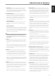
IDENTIFICATION OF CONTROLS
REAR PANEL
ATTENTION!
Please make sure that the C 356BEE is powered o or unplugged from the mains power source before making any connections. It is also advisable to power
down or unplug all associated components while making or breaking any signal or AC power connections.
1
19
432 5 6 7 8 9 10 12 16 17
18
15141311
120V Version
Model Only
8
ENGLISH PORTUGUÊSFRANÇAIS ESPAÑOL ITALIANO DEUTSCH NEDERLANDS SVENSKA РУССКИЙ