
Owner's Manual
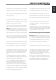

8 PRE OUT 1: The PRE OUT 1 sockets can be used to drive an additional
power amplier. Use a twin RCA-to-RCA lead to connect to the left and
right “Audio Input” of the Power amplier or processor to the PRE OUT 1
sockets.
Always turn the C 375BEE and associated external power ampliers OFF
before connecting or disconnecting anything to the PRE OUT 1 sockets.
The PRE OUT 1 output signal will be aected by the C 375BEE’s volume
and tone control settings.
9 MAIN IN: Connections to an external pre-amplier or processor, such
as a surround-sound decoder. In normal use, this should be connected
to PRE OUT 2 sockets with the links supplied. To connect your NAD
C 375BEE to external processor or pre-amplier, remove rst these links.
Use a twin RCA-to-RCA lead to connect the left and right “Audio Output”
of the pre-amp or processor to the Main In sockets.
Always turn the C 375BEE and associated external power ampliers OFF
before connecting or disconnecting anything to the MAIN IN sockets.
10 PRE OUT 2: Connections to an external power amplier or processor, such
as a surround-sound decoder. In normal use, this should be connected to
the Main In sockets with the links supplied. To connect your NAD C 375BEE
to external processor or amplier sections, remove rst these links. Use a
twin RCA-to-RCA lead to connect the left and right “Audio Input” of a power
amplier or processor to the PRE OUT 2 sockets.
Always turn the C 375BEE and associated external power ampliers OFF
before connecting or disconnecting anything to the PRE OUT 2 sockets.
The PRE OUT 2 output signal will be aected by the C 375BEE’s volume
and tone control settings.
11 VOLUME PRE OUT 2: The VOLUME PRE-OUT 2 control allows for
adjustment of the output level of the PRE OUT 2 sockets. Turn clockwise
to increase the PRE OUT 2 volume setting; counter clockwise to lower
it. When set to the maximum position, the output level will be identical
to that of the PRE OUT 1 sockets. Refer also to the item below about
“Bi-Amping”.
BI-AMPING
Some loudspeakers have separate connection terminals for the LF (Low
Frequency) and HF (High Frequency) sections of the speaker. This facility
allows to “Bi-Amp” these speakers, where a separate power amplier
is used for the LF and HF section, which may improve overall sound
quality.
The C 375BEE provides two sets of preamplier outputs (PRE OUT 1 and
PRE OUT 2) to facilitate the connections for Bi-Amping. Moreover, the level
from PRE OUT 2 can be reduced in relation to PRE OUT 1 to accommodate
power ampliers with dierent gain (amplication factor).
To set up the C 375BEE with power ampliers rst decide which power
amplier has the highest gain. This is easily done by comparing the
loudness level of the power ampliers in an identical system (keep the
volume control at the same level; use the same source and speakers).The
amplier that plays louder has the highest gain (note that this does not
need to be the more powerful amplier of the two). Connect the amplier
with highest gain to the PRE OUT 2 sockets; the other power amplier to
the PRE OUT 1 sockets. From the maximum level position, use the VOLUME
PRE OUT 2 control to reduce the output level of PRE OUT 2 so that the
volume level of both power ampliers is exactly matched.
12 BRIDGE MODE: The C 375BEE amplier can be congured to be
MONO (Bridge Mode), more than doubling its output power. This way,
the C 375BEE can be used as part of a high power stereo or home-
theatre system, by connecting additional power ampliers.
In BRIDGED MODE (switch at ON setting), the C 375BEE will produce
approximately 330W into an 8 ohm loudspeaker. In this mode, the
amplier sections will react as though the speaker impedance has been
halved. Low impedance speakers (under 8 ohms) are not recommended
when using Bridge Mode as these may cause the amplier’s thermal
cut-out to operate if played at high levels.
Set the BRIDGE MODE switch to the “ON” position and connect the
speaker to the terminals marked “L +” and “R+” ensuring that the “L+”
is connected to the “+” terminal of your loudspeaker and the “R+” is
connected to the loudspeaker’s “ - ” terminal. Connect the source to
the Left INPUT sockets.
The BRIDGE MODE indicator on the front panel will illuminate when the
C 375BEE is in Bridge mode. Return normal speaker connections (Refer
also to the item below about “SPEAKERS A,B”). and keep BRIDGE MODE
switch to “OFF” position for normal stereo listening.
NOTE
Do not connect anything to the Right Input socket when Bridge Mode is
selected.
13 SOFT CLIPPING™: Enables NAD’s proprietary Soft Clipping circuitry
on all channels. At [ON] position, Soft Clipping gently limits the output
of the C 375BEE to minimize audible distortion should the amplier be
over-driven. Soft Clipping may simply be left ON at all times to reduce
the likelihood of audible distortion from excessive volume settings.
However, for critical listening and to preserve optimum dynamics, you
may wish to defeat it by setting this switch to “OFF” position.
The SOFT CLIPPING indicator on the front panel will illuminate when
the C 375BEE is in Soft Clipping mode. See also below the item about
“POWERDRIVE”.
POWERDRIVE
The C 375BEE uses NAD’s proprietary PowerDrive™ amplier technology
for all channels to preserve accurate, linear reproduction regardless
of the loudspeaker. This uniquely ecient power-supply topology
provides the real-world benets of high dynamic power that remains
uncompromised by low-impedance speakers.
By adding a second high-voltage rail to our well regulated high-current
power supply, we get an “overdrive” that can nearly double the continuous
power on a short term dynamic power basis. PowerDrive oers greater
amplier stability and low impedance drive capability, resulting in less
distortion when driving real speakers with real program material.
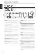
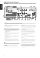
IDENTIFICATION OF CONTROLS
REAR PANEL
9
ENGLISHFRANÇAISESPAÑOLITALIANODEUTSCHNEDERLANDSSVENSKAРУССКИЙ