
Owner's Manual


7 ZONE 2
• Sends zone selected audio source to the corresponding audio input
of another zone. Use high quality patch cables to reduce noise
pickup over long distance runs.
• For a better understanding of zone settings, study below the section
about “Zone Controls” of the “Main Menu” discussion as well as the
item about “Zone Setup” under the “Setup Menu” literatures.
8 FM ANTENNA TERMINAL
• The supplied wire “dipole” FM antenna will connect to the FM
connector using the supplied “balun” adapter. It will usually work
best when mounted on a vertical surface such as a wall, with arms
fully outstretched forming a horizontal “T” perpendicular to the
origin point of the signal.
AM ANTENNA TERMINAL
The AM loop antenna supplied with the T 757 (or a suitable
replacement) is required for AM reception.
• Connect the supplied AM loop antenna to these terminals. If an
external AM antenna is used, make connections to the AM and GND
terminals in accordance with the instructions supplied with the
antenna.
• Testing dierent positions for the antenna may improve reception;
vertical orientation will usually produce the best results. Antenna
proximity to large metal objects (appliances, radiators) may impair
reception, as will as attempts to lengthen the wire to the loop.
• Refer also to the item about ASSEMBLING THE LOOP ANTENNA at
the LISTENING TO AM/FM RADIO section of the OPERATION page.
9 SPEAKERS
• Connect the respective speaker’s FRONT L, FRONT R, CENTER,
SURR R, SURR L, SURR-BACK L, and SURR-BACK R channels to their
corresponding loudspeakers. Make sure the “+” (red) terminal and
“-” (black) terminal are connected to the corresponding “+” and “-”
terminals of the loudspeaker. Use extra care to ensure that no stray
wires or strands cross between posts or terminals at either end.
• The T 757 is designed to produce optimum sound quality when
connected to speakers with impedances within its operating range.
Please make sure that all the speakers are rated 8 ohms minimum
per speaker.
NOTE
Use stranded wire of at least 16 gauge (AWG). Connections to the T 757 can
be made with banana-type plugs. Bare wire or pins can also be used by
loosening the terminal’s plastic nut, making a clean, neat connection, and
re-tightening carefully. To minimize the danger of short circuit, ensure that
only 1/2-inch of exposed wire or pin is employed when connecting.
10 AC MAINS INPUT
The T 757 comes supplied with a separate detachable mains power
cord. Before connecting the plug to the mains power source, ensure
that it is rmly connected to the T 757’s AC Mains input socket rst.
• Connect only to the prescribed AC outlet, i.e., 120V 60 Hz (for 120V
version models only) or 230V 50 Hz (for 230V version models only).
• Always disconnect the mains power plug from the mains power
source rst, before disconnecting the cable from the T 757’s AC
Mains input socket.
11 HDMI (HDMI 1-4, HDMI MONITOR OUT)
• Connect the sets of HDMI input to the HDMI OUT connectors of
source components such as DVD player, BD player or HDTV satellite/
cable box. Connect the HDMI Monitor OUT to a HDTV or projector
with HDMI input.
WARNING
Before connecting and disconnecting any HDMI cables, both the T 757
and the ancillary source must be powered OFF and unplugged from the
AC outlet. Failure to observe this practice may cause permanent damage
to all equipment connected via HDMI sockets.
12 MP DOCK
The T 757 is equipped with a data port in the rear panel where an
optional NAD IPD (NAD IPD Dock for iPod) 1, NAD IPD 2 and later
variants can be plugged in.
• Connect the “MP DOCK (DATA PORT)” jack of the T 757 to the
corresponding “DATA PORT” socket of the optional NAD IPD model.
• AUDIO 3 and S-VIDEO 1 are the assigned default ports for the audio/
video output of the separately sold NAD IPD (NAD IPD Dock for
iPod) 1, NAD IPD 2 and later variants.
• Refer also to the “LISTENING TO YOUR iPod PLAYER” segment of the
“OPERATION” section.
NOTE
The NAD IPD Dock for iPod is not supplied with your T 757.
13 +12V TRIGGER OUT
The +12V TRIGGER OUT is used for controlling external equipment that
is equipped with a +12V trigger input.
• Connect this +12V TRIGGER OUT to the other equipment’s
corresponding +12V DC input jack using a mono cable with 3.5mm
male plug.
• This output will be 12V when the T 757 is ON and 0V when the unit
is either OFF or in standby mode.
14 IR IN/IR OUT 1-2
• These mini-jacks accept and output remote-controlled codes in
electrical format, using industry-standard protocols, for use with
“IR-repeater” and multi-room systems and related technologies.
• All NAD products with IR IN/IR OUT features are fully compatible
with the T 757. For non-NAD models, please check with your other
product’s service specialists as to their compatibility to the T 757’s IR
features.
IR IN: This input is connected to the output of an IR (infrared) repeater
(Xantech or similar) or the IR output of another component to allow
control of the T 757 from a remote location.
IR OUT 1, IR OUT 2: When connected to the IR IN of an ancillary
equipment, direct the ancillary equipment’s own remote control to the
T 757’s infrared receiver to command or control the linked unit.
IR IN and IR OUT 1, IR OUT 2: Connect the T 757’s IR IN to the IR OUT
of an ancillary equipment. Connect also the T 757’s IR OUT 1 to another
equipment with IR IN feature. With this setup, the T 757 acts as an “IR-
repeater” allowing the equipment connected to the T 757’ s IR IN control
or command of the other equipment linked to the T 757’s IR OUT 1. A
combination of IR IN and IR OUT 2 also perform the same function.
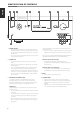
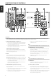
IDENTIFICATION OF CONTROLS
REAR PANEL
9
ENGLISHPORTUGUÊS FRANÇAISESPAÑOLITALIANODEUTSCHNEDERLANDSSVENSKAРУССКИЙ