
Operation Manual


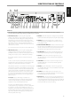


12 TAPE MONITOR IN/OUT: Connections for analog recording and
playback to a secondary audio tape recorder of any type. Using twin
RCA-to-RCA leads, connect to the left and right “Audio Output” of
the tape machine to the TAPE MONITOR IN sockets for playback and
tape monitoring. Connect the left and right “Audio Input” of the tape
machine to the TAPE MONITOR OUT sockets for recording.
TO MAKE A RECORDING
When any source is selected, its signal is also fed directly to any tape
machine connected to the TAPE 2 OUT or TAPE MONITOR OUT for
recording.
TAPE TO TAPE COPYING
You can copy between two tape machines connected to your NAD
C 165BEE. Put the source tape in the recorder connected to Tape 2
and the blank tape into the recorder connected to Tape Monitor. By
selecting TAPE 2 input you can now record from Tape 2 to Tape Monitor
and monitor the signal coming from the original tape.
NOTE
There will be no Tape 2 output when Tape 2 (or Tape Monitor OUT when
Tape Monitor) is the selected source input. This prevents feedback
through the recording component thereby preventing possible damage
to your speakers.
13 PRE OUT 1: Connections to an external power amplier or processor,
such as a surround-sound decoder. Use a twin RCA-to-RCA lead
to connect the left and right “Audio Input” of a power amplier or
processor to the PRE OUT 1 sockets.
Always turn the C 165BEE and associated external power ampliers OFF
before connecting or disconnecting anything to the PRE OUT 1 sockets.
The PRE OUT 1 output signal will be aected by the C 165BEE’s volume
and tone control settings.
14 PRE OUT 2: The PRE OUT 2 sockets can be used to drive an additional
power amplier. Use a twin RCA-to-RCA lead to connect to the left and
right “Audio Input” of the Power amplier or processor to the PRE OUT
2 sockets. The rear panel VOLUME can be used to reduce PRE OUT 2
output level by up to -12 dB. With the rear panel VOLUME set to the
maximum position (0 dB position), the PRE OUT 2 output level will be
identical to that of the PRE OUT 1 sockets.
Use a twin RCA-to-RCA lead to connect the left and right “Audio Input”
of a power amplier or processor to the PRE OUT 2 sockets. Always
turn the C 165BEE and associated external power ampliers OFF before
connecting or disconnecting anything to the PRE OUT 2 sockets. The
PRE OUT 2 output signal will be aected by the C 165BEE’s volume and
tone control settings.
15 SUBW: Connect to a powered (“active”) subwoofer or to power
amplier channels driving a passive system.
16 VOLUME: The rear-panel VOLUME control allows for adjustment of the
output level of the PRE OUT 2 sockets. Turn clockwise to increase the PRE
OUT 2 volume setting; counter clockwise to lower it. When set to the
maximum position, the output level will be identical to that of the PRE OUT
1 sockets. Refer also the item below about “Bi-Amping”.
BI-AMPING
Some loudspeakers have separate connection terminals for the LF (Low
Frequency) and HF (High Frequency) sections of the speaker. This facility
allows to “Bi-Amp” these speakers, where a separate power amplier is used
for the LF and HF section, which may improve overall sound quality.
The C 165BEE provides two sets of preamplier outputs (PRE OUT 1 and
PRE OUT 2) to facilitate the connections for Bi-Amping. Moreover, the level
from PRE OUT 2 can be reduced in relation to PRE OUT 1 to accommodate
power ampliers with dierent gain (amplication factor).
To set up the C 165BEE with power ampliers rst decide which power
amplier has the highest gain. This is easily done by comparing the
loudness level of the power ampliers in an identical system (keep the
volume control at the same level; use the same source and speakers).The
amplier that plays louder has the highest gain (note that this does not
need to be the more powerful amplier of the two). Connect the amplier
with highest gain to the PRE OUT 2 sockets; the other power amplier to
the PRE OUT 1 sockets. From the maximum level position, use the rear
panel VOLUME control to reduce the output level of PRE OUT 2 so that the
volume level of both power ampliers is exactly matched.
17 IR IN/OUT: These mini-jacks accept and output remote-controlled
codes in electrical format, using industry-standard protocols, for use
with “IR-repeater” and multi-room systems and related technologies.
IR IN: This input is connected to the output of an IR (infrared) repeater
(Xantech or similar) or the IR output of another component to allow
control of the C 165BEE from a remote location.
IR OUT: When connected to the IR IN of an ancillary equipment, direct
the ancillary equipment’s own remote control to the C 165BEE’s infrared
receiver to command or control the linked unit.
All NAD products with IR IN/IR OUT features are fully compatible with
the C 165BEE. For non-NAD models, please check with your other
product’s service specialists as to their compatibility with the C 165BEE’s
IR features.
18 +12V TRIGGER OUT: The +12V TRIGGER OUT is used for controlling
external equipment that is equipped with a +12V trigger input. This output
will be 12V when the C 165BEE is ON and 0V when the unit is either OFF or
in standby. This output can drive a load up to 50mA at 12V.
IDENTIFICATION OF CONTROLS
REAR PANEL
8
ENGLISH FRANÇAIS ESPAÑOL ITALIANO DEUTSCH NEDERLANDS SVENSKA РУССКИЙ