
Operation Manual

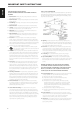


1 FM ANTENNA TERMINAL
• Connect the supplied wire “dipole” FM antenna to the FM antenna
terminal using the supplied “balun” adapter. It will usually work best
when mounted on a vertical surface such as a wall, with arms fully
outstretched forming a horizontal “T” perpendicular to the origin
point of the signal.
AM ANTENNA TERMINAL
• The AM loop antenna supplied with the C 427 (or a suitable
replacement) is required for AM reception. Open the clip terminal
lever; insert the wire making sure to match the color-coded (white
and black) ends of the wire to that of the terminal and close the
lever ensuring that the lever locks the wire in place.
• Testing dierent positions for the antenna may improve reception;
vertical orientation will usually produce the best results. Antenna
proximity to large metal objects (appliances, radiators) may impair
reception, as will attempts to lengthen the wire to the loop.
• If an external AM antenna is used, make connections to the AM
and GND terminals in accordance with the instructions supplied
with the antenna. Refer also to the item about ASSEMBLING THE
LOOP ANTENNA at the LISTENING TO AM/FM RADIO section of the
OPERATION page.
2 AUDIO OUT (L, R)
• Connect to the corresponding analog audio input of an amplier,
receiver or stereo system.
3 RS-232
• Connect this interface using RS-232 serial cable (not supplied) to
any Windows compatible PC to allow remote control of the C427
via compatible external controllers.
• NAD is a certied partner of AMX and Crestron and fully supports
these external devices. Check out the NAD website for information
about AMX and Crestron compatibility with NAD. See your NAD
audio specialist for more information.
• Refer to the NAD website for information about RS232 Protocol
documents and PC interface program.
4 IR IN
• This input is connected to the output of an IR (infrared) repeater
(Xantech or similar) or the IR output of another component to allow
control of the C 427 from a remote location.
• Most NAD products with IR OUT are fully compatible with the C 427.
5 +12V TRIGGER IN
• This input allows the C 427 to be switched remotely to standby
mode and ON by ancillary equipment, such as an amplier, preamp,
AV processor, etc. The controlling device must be equipped with a
12V trigger output to use this feature.
• Connect this +12V trigger input to the remote component’s
corresponding +12V DC output jack using a mono cable with
3.5mm male plug.
6 POWER
• Supply the AC mains power to the C 427.
• When the POWER switch is set to ON position, the C 427 goes to
standby mode as shown by the amber status condition of the
Standby LED. Press the front panel Standby button or remote
control’s [ON] button to switch ON the C 427 from standby mode.
• If you intend not to use the C 427 for long periods of time (such as
when on vacation), switch o the POWER switch.
• With POWER switched o, neither the front panel Standby button
nor remote control’s [ON] button can activate the C 427.
7 AC MAINS INPUT
• The C 427 comes supplied with a separate detachable AC power
cord. Connect corresponding end of the AC power cord to the AC
mains input of the C 427 and the plug connected to a mains power
source.
• Connect only to the prescribed mains power source, i.e., 120V 60
Hz (for 120V version models of C 427 only) or 230V 50 Hz (for 230V
version models of C 427 only).
• Always disconnect the plug from the mains power source rst,
before disconnecting the other end of the AC power cord from the
C 427’s AC Mains input socket.
• If you intend not to use the C 427 for long periods of time,
disconnect the plug from the mains power source.
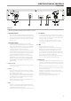
IDENTIFICATION OF CONTROLS
REAR PANEL
© NAD C 427
FM
ANTENNA
GND AM
AUDIO OUT
RS232
+12V
TRIGGER
IN
POWER
100~240V – 50/60Hz
ON
IR IN
L
R
2 3 54 61
7
ATTENTION!
Please make sure that the C 427 is powered o or unplugged before making any connections. It is also advisable to power down or unplug all associated
components while making or breaking any signal or AC power connections.
7
ENGLISHPORTUGUÊS FRANÇAISESPAÑOLITALIANODEUTSCHNEDERLANDSSVENSKAРУССКИЙ