
Operation Manual

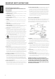
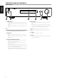


1 STANDBY BUTTON
• Press this button to switch ON the C 510 from standby mode. The
Standby LED indicator will turn from amber to blue and illuminate
the VFD.
• Pressing the STANDBY button again turns the unit back to standby
mode.
NOTE
In order to turn ON the C 510 from standby mode or back to standby
mode, the rear panel POWER switch must be in the ON position.
2 STANDBY LED
• This indicator will light up amber when the C 510 is at standby
mode.
• When the C 510 is powered up from standby mode, this indicator
will illuminate blue.
3 VACUUM FLUORESCENT DISPLAY (VFD)
• Display visual information about the current Source. Information
supplied is generated by the Source.
• Provide also visual information about C 510’s other functions,
settings and indicators.
• “Unlock” is shown among the information displayed if no source
input is connected to the particular Source. If a connected source is
detected, the sampling rate will be displayed.
• Toggle remote control's [DIM] button to cycle through various levels
of display brightness that also includes turning o the display.
4 REMOTE SENSOR
• Point the DR 1 remote control at the remote sensor and press the
buttons.
• Do not expose the remote sensor of the C 510 to a strong light
source such as direct sunlight or illumination. If you do so, you may
not be able to operate the C 510 with the remote control.
Distance: About 23ft (7m) from the front of the remote sensor.
Angle: About 30° in each direction of the front of the remote sensor.
5 a SOURCE s
• Toggle to select through the Sources.
6 VOLUME
• Use this control to adjust the overall loudness of the output signal
via 2-CHANNEL AUDIO OUT.
IDENTIFICATION OF CONTROLS
FRONT PANEL
© NAD C510
4 51 2 3 6
6
ENGLISH FRANÇAIS ESPAÑOL ITALIANO DEUTSCH NEDERLANDS SVENSK A РУССКИЙ