
Owner`s manual


IDENTIFICATION OF CONTROLS
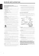
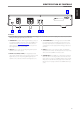
REAR PANEL
1 UPGRADE PORT: For future software program updates, use this port
to upgrade the C 545BEE. Owners who register their C 545BEE in our
international website www.nadelectronics.com will be advised of
updates (if any). Your custom installer or dealer can assist you in the
proper upgrade and setup of your C 545BEE.
2 LINE OUT: Connect to the corresponding analog audio input of an
amplier, receiver or stereo system.
3 DIGITAL OUT (COAXIAL, OPTICAL): The digital playback audio
output signal is available at these ports. Connect the optical or coaxial
digital OUT ports to the corresponding S/PDIF digital input of an
amplier, receiver, computer soundcard or other digital processors.
4 +12V TRIGGER INPUT: The +12V Trigger input allows the C 545BEE
to be switched remotely from standby mode to ON and vice-versa
by ancillary equipment such as a preamplier, AV processor, etc. The
controlling device must be equipped with a 12V trigger output to use
this feature.
5 IR INPUT: This input is connected to the output of an IR (infrared)
repeater (Xantech or similar) or the IR output of another component to
allow control of the C 545BEE from a remote location.
6 AC MAINS INPUT: The C 545BEE comes supplied with a separate AC
Mains cable. Before connecting the cable to a live wall socket ensure
that it is rmly connected to the C 545BEE’s AC Mains input socket rst.
Always disconnect the AC Mains cable plug from the live wall socket
rst, before disconnecting the cable from the C 545BEE’s Mains input
socket.
ATTENTION!
Please make all the connections to your C 545BEE with the unit unplugged. It is also advisable to power down or unplug all associated components while
making or breaking any signal or AC power connections.
1 2 3 4 5
6
9
ENGLISHFRANÇAISESPAÑOLITALIANODEUTSCHNEDERLANDSSVENSKAРУССКИЙ