CI 8-150 DSP ENGLISH ® Multi-Channel Amplifier © NAD CI 8-150 DSP Owner’s Manual
IMPORTANT SAFETY INSTRUCTIONS ENGLISH • • • • • • • • • • • • • • • • • • • • 2 Read instructions - All the safety and operating instructions should be read before the product is operated. Retain instructions - The safety and operating instructions should be retained for future reference. Heed Warnings - All warnings on the product and in the operating instructions should be adhered to. Follow Instructions - All operating and use instructions should be followed.
IMPORTANT SAFETY INSTRUCTIONS CAUTION • Changes or modifications to this equipment not expressly approved by NAD Electronics for compliance could void the user’s authority to operate this equipment. • To prevent electric shock, match wide blade of plug to wide slot, fully insert. • Marking and rating plate can be found at the rear panel of the apparatus. • To reduce the risk of fire or electric shock, do not expose this apparatus to rain or moisture.
GETTING STARTED ENGLISH WHAT’S IN THE BOX Packed with your CI 8‑150 you will find • Two detachable mains power cord • 4 pieces of 4-position terminal block (for SPEAKERS) • 1 piece of 4-position terminal block (for IR IN/OUT) • 1 piece of 2-position terminal block (for +12V TRIGGER IN) • 4 pieces of feet with mounting screws • Quick Setup Guide QUICK START Refer to the supplied CI 8‑150 Quick Setup Guide for basic instructions in setting up your new NAD CI 8‑150.
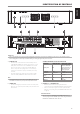
ENGLISH IDENTIFICATION OF CONTROLS © NAD CI 8-150 DSP 1 2 3 4 3 5 6 7 © NAD CI 8-150 DSP 8 9 10 11 12 13 ATTENTION! Please ensure that the CI 8‑150 is powered off or unplugged from the mains power outlet before making any connections. It is also advisable to power down or unplug all associated components while making or breaking any signal or AC power connections. 1 POWER BUTTON • Press this button to switch ON CI 8‑150 from standby mode.
IDENTIFICATION OF CONTROLS ENGLISH 4 OPTICAL IN 1-2/COAXIAL IN 1-2 • Use applicable connectors (not supplied) to connect OPTICAL IN 1-2 and/or COAXIAL IN 1-2 terminals to corresponding Digital Audio Output terminals of compatible external devices such as preamplifiers, processors or other applicable devices. • Configure LINE INPUT 1-8 via INPUT/OUTPUT menu of the webbased CI 8‑150 User Interface.
10 IR IN/OUT • Use the supplied IR IN/OUT terminal block to connect IR OUT terminals to compatible external IR IN source and IR IN terminals to the output of external IR (infrared) repeater (Xantech or similar) or IR output of compatible devices. Install the wired up IR IN/OUT terminal block to CI 8‑150’s IR IN/OUT rear panel terminal.
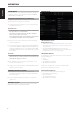
OPERATION ENGLISH USER INTERFACE IDENTIFICATION The CI 8‑150 can be accessed, configured and managed via a web-based User Interface. Start access to your CI 8‑150 by following the GUIDELINE FOR NETWORK SETUP CONNECTION. GUIDELINE FOR NETWORK SETUP CONNECTION This guideline is applicable to PC, MAC or smartphone control devices. Adapt the guidelines according to your control device. 1 Use an Ethernet cable (not supplied) to connect CI 8‑150’s LAN port to your Wired network or router.
NETWORK ID DHCP DHCP setting controls IP Address allocation. • DHCP On: Current IP Address is displayed. Your router dynamically assigns the IP address but may change each time CI 8‑150 is powered up. • DHCP Off: Static IP address can be manually assigned. Perform a network scan to identify unused IP address within the range of your router. Ensure that a correct IP Address is entered; otherwise, your CI 8‑150 becomes inaccessible.
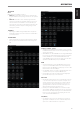
OPERATION ENGLISH OUTPUT SETUP DSP NAME • The factory default names of the eight OUTPUT channels are Output 1 up to Output 8. Each OUTPUT channel can be renamed by directly typing over the specific OUTPUT. For example, type over “OUTPUT 1” with the desired name or label like “Living Room”. • The eight OUTPUT channels correspond to the SPEAKERS 1 to 8 respectively. INPUT • Each OUTPUT channel can be assigned any of the INPUT channels (Line 1-8, Optical 1-2 and Coaxial 1-2).
SAVE PRESET(S) SAVE PRESET(S) involve a combination of EDITING, adjusting, setting and saving desired Slope, Q, Frequency and Gain settings. Undertake the following steps to SAVE PRESET(S). ENGLISH OPERATION 3 Select “Save Preset(s)” to save above Preset 1 settings. 1 Select desired Preset number you would like to save your DSP settings. For this example, we will select “Preset 1”. 4 Select “Preset 1”.
OPERATION ENGLISH LOAD PRESET(S) Select LOAD PRESET(S) to upload saved Preset settings/files to your amplifier. Undertake the following steps to LOAD PRESET(S). 1 Select “Load Preset(s)” to load a saved Preset file to a desired Preset number. PRESET EDITING DUPLICATE/FROM/TO • Select FROM drop down tab the Preset number you will copy TO another Preset number. For example, select “Preset 1” from FROM drop down tab and then select from TO drop down tab “Preset 2”.
Q • “Q” setting refers to the depth the bandwidth can be adjusted. ”Q” level is from 0.1 up to 24. Bandwidth is wider at lower Q level and narrower with higher Q level. GAIN • Grab the pointer of the “Gain” knob icon and rotate to set the dB level the selected frequency can be increased or decreased. Gain level can be set up to 12 dB. The corresponding numerical value of adjusted dB level is reflected beside the knob icon.
OPERATION ENGLISH ALWAYS ON • CI 8‑150 will always be powered up and at operating mode. The unit can only be normally powered down by switching to Power Button method or unplugging the AC power cord from the mains power outlet. • Power consumption is more than 80W while the unit remains powered up. 12V TRIGGER • The function of powering up/down the CI 8‑150 is dependent upon the presence or absence of +12V DC supply at +12V TRIGGER IN (refer also to item about +12V TRIGGER IN).
ENGLISH OPERATION STANDBY MODES STANDBY MODE CONDITION Standby Mode 1 (Power Button) Method A • ECO mode : ON • Power mode: Switch from other Power Mode (Always ON, 12V Trigger, Signal Sense) to Power Button RESULT • Unit will immediately go to standby mode after the switch to Power Button mode.
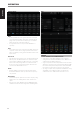
OPERATION ENGLISH DIAGNOSTICS ACTIONS INTERNAL TEMPERATURE • Measurement reading of internal temperature is displayed. Unit of temperature can be displayed in either Celsius or Fahrenheit. CHECK FOR UPDATES • Select “Check for Updates” to check for any new firmware update. If new firmware details are shown, continue on with the upgrade prompt instructions to complete the upgrade process.
ENGLISH SPECIFICATIONS All specs are measured according to IHF 202 CEA 490-AR-2008 standard. THD is measured using AP AUX 0025 passive filter and AES 17 active filter.
SPECIFICATIONS ENGLISH POWER CONSUMPTION AND HEAT OUTPUT CONDITION Eco Mode Standby Power at 8 ohms Network Standby Power at 8 ohms Idle power at 8 ohms 1/8 rated power Output power at 8 ohms, all 1/3 rated power channels driven 1/2 rated power Full rated power 1/8 rated power Output power at 4 ohms, all 1/3 rated power channels driven 1/2 rated power Full rated power 230 V/50 HZ POWER CONSUMPTION HEAT OUTPUT (BTU/HR) (W) 0.4 1.4 1.2 4.
ENGLISH
www.NADelectronics.com ©2021 NAD ELECTRONICS INTERNATIONAL A DIVISION OF LENBROOK INDUSTRIES LIMITED All rights reserved. NAD and the NAD logo are trademarks of NAD Electronics International, a division of Lenbrook Industries Limited. No part of this publication may be reproduced, stored or transmitted in any form without the written permission of NAD Electronics International.