Integrating the Cisco Catalyst Blade Switch 3020 for the HP c-Class BladeSystem into the Cisco Data Center Network Architecture Design Guide © 2008 Cisco Systems, Inc. All rights reserved. This document is Cisco Public Information.
Design Guide Contents Introduction ..................................................................................................................................... 3 HP c-Class BladeSystem Enclosure Overview ............................................................................. 3 Cisco Catalyst Blade Switch 3020 for HP...................................................................................... 5 Cisco Catalyst Blade Switch 3020 Features ................................................
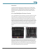
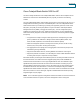
Design Guide Introduction This guide provides best design practices for deploying the Cisco® Catalyst® Blade Switch 3020 for the HP c-Class BladeSystem enclosure within the Cisco Data Center Networking Architecture. It describes the internal components of the blade-server enclosure and Cisco Catalyst Blade Switch 3020 and explores different methods of deployment.
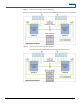
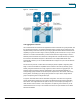
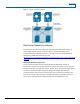
Design Guide Figure 2. Enclosure Interconnections Using Full-Height Servers Figure 3. Enclosure Interconnections Using Half-Height Servers © 2008 Cisco Systems, Inc. All rights reserved. This document is Cisco Public Information.
Design Guide Cisco Catalyst Blade Switch 3020 for HP This section briefly describes the Cisco Catalyst Blade Switch 3020 for HP and explains how the blade servers within the HP c-Class BladeSystem are physically connected to the switching modules. The Cisco Catalyst Blade Switch 3020 provides enhanced Layer 2 services (known as Layer 2+ or Intelligent Ethernet switching) to the HP c-Class BladeSystem.
Design Guide Cisco Catalyst Blade Switch 3020 Features This section highlights information about the protocols and features provided by the Cisco Catalyst Blade Switch 3020 that help integrate the HP c-Class BladeSystem enclosure into the Cisco Data Center Network Architecture. Spanning Tree The Cisco Catalyst Blade Switch 3020 supports different versions of the Spanning Tree Protocol and associated features, including the following: ● Rapid Spanning Tree Protocol (RSTP), based on IEEE 802.
Design Guide A scenario wherein BPDUs are lost may be caused by unidirectional links, which can cause Layer 2 loops. To prevent this problem, use Loop Guard and UDLD. Loop Guard prevents a port from forwarding as a result of missed BPDUs, which might cause a Layer 2 loop that could bring down the network. UDLD allows devices to monitor the physical configuration of fiberoptic or copper Ethernet cables and detect when a unidirectional link exists.
Design Guide Note: The IEEE 802.1w protocol is enabled by default when running spanning tree in RPVST+ or MST mode on the Cisco Catalyst Blade Switch 3020. The Cisco Catalyst Blade Switch 3020 enables PVST+ for VLAN 1 by default. The Spanning Tree Protocol uses the path cost value to determine the shortest distance to the root bridge. The port path cost value represents the media speed of the link and is configurable on a per-interface basis, including Cisco EtherChannel interfaces.
Design Guide Figure 5. RSPAN Example Link Aggregation Protocols Cisco Fast EtherChannel interfaces and Gigabit EtherChannel interfaces are logically bundled, and they provide link redundancy and scalable bandwidth between network devices. PAgP and LACP help automatically create these channels by exchanging packets between Ethernet interfaces and negotiating a logical connection.
Design Guide Figure 6. Alternative Network Configuration Data Center Network Architecture The architecture of the data center infrastructure must address the requirements necessary to create a highly available, scalable, and secure network. This section describes the basic architecture necessary to meet these goals. It is a synopsis of the Cisco Data Center Network Architecture; for details about this architecture, visit: http://www.cisco.
Design Guide Figure 7. Data Center Front-End Network Aggregation Layer The aggregation layer is a point of convergence for network traffic that provides connectivity between server farms and the rest of the enterprise. The aggregation layer supports Layer 2 and Layer 3 functions and presents an ideal location for deploying centralized application, security, and management services.
Design Guide Layer 2 adjacency in the server farm allows for the deployment of servers or clusters that require the exchange of information done at Layer 2 only. It also readily supports access to network services in the aggregation layer such as load balancers and firewalls, enabling an efficient use of shared, centralized network services by the server farms.
Design Guide link redundancy combined with a deterministic topology design to achieve application-availability requirements. Servers are typically configured with multiple NICs and dual homed to the access layer switches to provide backup connectivity to the business application. High availability is an important design consideration in the data center. The Cisco Catalyst Blade Switch 3020 has numerous features and characteristics that contribute to a reliable, highly available network.
Design Guide ● Network Fault Tolerance (NFT) ● Transmit Load Balancing (TLB) ● Switch Assisted Load Balancing (server load balancing [SLB]) NFT teaming creates a virtual interface by grouping the blade-server network adapters into a team. One adapter is the primary active interface and all other adapters are in a standby state. The virtual adapter uses a single MAC address and a single Layer 3 address.
Design Guide Slot Count The data center infrastructure must be flexible enough to allow growth in both server capacity and service performance. Connecting a blade system directly into the aggregation layer places more significance on the number of slots available to accommodate blade-system uplinks and integrated services. Traditionally, the access layer provides the port density necessary to allow the physical growth of server farms.
Design Guide The data center core is a mechanism to replicate and horizontally scale the data center environment. In the recommended design the aggregation and access layers are regarded as a module that can be duplicated to extend the enterprise. Each data center module provides its own network services locally in the aggregation switches. This approach allows the network administrator to determine the limits of each data center module and replicate as necessary.
Design Guide The Cisco Catalyst Blade Switch 3020 contains an additional Fast Ethernet port, which connects to the HP c-Class BladeSystem Onboard Administrator, providing OOB management using the insight manager interface. The user may also use this path to access the CLI functions of the switch, transfer SNMP information, and upload software images and configuration files. This path is independent of the switch fabric.
Design Guide Management Options The Cisco Catalyst Blade Switch 3020 switch is manageable with the following methods: ● HTTP-based device-manager GUI ● SNMP-based management applications ● Cisco IOS Software CLI The embedded device manager on the Cisco Catalyst Blade Switch 3020 provides a GUI to configure and monitor the switch through a Web browser. This scenario requires using either inband or out-of-band management and enabling the HTTP or HTTPS server on the switch.
Design Guide Network Topologies Using the Cisco Catalyst Blade Switch 3020 This section discusses the following physical topologies: ● Recommended topology: Classic V-shaped topology with Spanning Tree Protocol ● Alternative topology: Square topology with Spanning Tree Protocol These network designs emphasize high availability in the data center by eliminating any single point of failure and by providing deterministic traffic patterns and predictable behavior during times of network convergence.
Design Guide ● Primary root switch failure and recovery ● Secondary root switch failure and recovery These tests revealed the intricacies of fast convergence in the data center and the necessity for a holistic approach to high availability. Test cases that did not involve the failure of the active HSRP aggregation switch resulted in an average failover time of about 1 second.
Design Guide RSPAN requires a VLAN to carry the mirrored traffic to the remote destination switch. In the recommended topology, the secondary aggregation switch is the RSPAN destination, where an analysis device, such as the integrated Cisco Network Analysis Module (NAM), resides. The RSPAN VLAN uses the uplink between the blade switch and the secondary aggregation switch. This uplink is blocking under normal conditions for regular VLANs.
Design Guide Step 2. Allow only those VLANs that are necessary on the port channel between the aggregate and the blade switches. Use the switchport trunk allowed vlan vlanID command to configure the port-channel interfaces of the aggregate switch to allow only those VLANs indicated with the vlanID option. Additional Cisco Catalyst Blade Switch 3020 Configuration Step 1. Enable BPDU Guard on the internal server ports of the switch.
Design Guide This design supports traffic monitoring using SPAN or RSPAN. For example, a network-analysis device connected to the external ports on the front of the Cisco Catalyst Blade Switch 3020 may capture locally mirrored traffic. Alternatively, RSPAN traffic can be carried on the Cisco Catalyst Blade Switch 3020 uplinks if bandwidth usage is not a concern. For the steps to configure traffic monitoring, refer to the “Configuration Details” section.
Design Guide VLAN Configuration To configure the VLANs on the switches, complete the following tasks: Set the VTP administrative domain name and mode and create the server-farm VLANs as follows: (config)# vtp domain (config)# vtp mode transparent (config)# vlan 60 (config-vlan)# name bladeservers (config-vlan)# state active RPVST+ Configuration Configure Spanning Tree Protocol to manage the physical loops in the topology.
Design Guide (config-if)# channel-group 1 mode active Configure the passive LACP members on Cisco Catalyst Blade Switch 3020 switch A as follows: (config) # interface GigabitEthernet0/19 (config-if)# description <<** Connected to Aggregation-1 **>> (config-if)# channel-group 1 mode on (config) # interface GigabitEthernet0/20 (config-if)# description <<** Connected to Aggregation-1 **>> (config-if)# channel-group 1 mode on Trunking Configuration Use the following guidelines when configuring trunks: ● Allo
Design Guide Server-Port Configuration A blade server is assigned a specific port on the blade switch. This assignment is predetermined by the physical slot the blade server occupies in the enclosure. Table 1 correlates the server and switch ports. Table 1.
Design Guide interface GigabitEthernet0/1 description <<** BladeServer-1 **>> switchport trunk encapsulation dot1q switchport trunk allowed vlan 10,60 switchport mode trunk switchport port-security aging time 20 switchport port-security maximum 1 vlan 10,60 no cdp enable spanning-tree portfast trunk spanning-tree bpduguard enable end Server Default Gateway Configuration The default gateway for a server is a Layer 3 device located in the aggregation layer of the data center.
Design Guide RSPAN Configuration RSPAN allows for remote traffic monitoring in the data center. Define source and destination sessions to mirror interesting traffic to a remote VLAN captured by network-analysis tools. Configure a VLAN for RSPAN on the Cisco Catalyst Blade Switch 3020 and the aggregate switch as follows: (config)# vlan (config-vlan)# name (config-vlan)# remote-span Create a source session as follows.