
Operation Manual

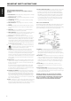

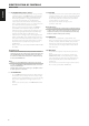

AUTOMATED TURN-ON LOGIC (ATO LOGIC)
The CI 940 may be turned ON in three discrete ways for complete system
exibility - from the front panel standby button, the 12V-TRIGGER circuit or
by the input signal-sensing circuit. The ON/OFF power control is managed
by the Automated Turn-On logic or ATO Logic circuit that requires the
CI 940 to be switched back to standby mode in the same manner it was
activated. In other words, if the CI 940 is switched ON via a +12V-control
signal, it cannot be switched to standby mode via the front panel STANDBY
button, it must wait for removal of the +12V-control signal. In practice, you
probably would use only one of the methods once your CI 940 is installed.
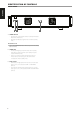
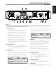
IDENTIFICATION OF CONTROLS
REAR PANEL
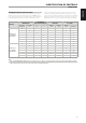
CONDITION
STANDBY BUTTON
+12V TRIGGER IN
(using 3.5mm mini-jack plug)
INPUT SENSE CI 940 STATUS
Press to enter
Standby mode
Press to turn
ON
+12V 0V
Input sense
>20 mV
Input sense
<20 mV
Operating
mode
Standby mode
POWER switch : ON
+12V TRIGGER IN/
INPUT SENSE: OFF
✓ ✓
✓ ✓
✓ ✓
✓ ✓
✓
✓ ✓
✓ ✓
POWER switch : ON
+12V TRIGGER IN/
INPUT SENSE: AUTO
✓ ✓
✓ ✓
✓ ✓
✓ ✓
✓
✓ ✓
✓ ✓
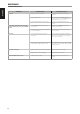
NOTE
If the +12V TRIGGER IN/INPUT SENSE switch is set to OFF, the presence or absence of +12V trigger input or any input signal at the ZONE 1 INPUT or ZONE 2
INPUT terminals will not have any eect on the CI 940, eectively defeating both features.
9
ENGLISHFRANÇAISESPAÑOLITALIANODEUTSCHNEDERLANDSSVENSKAРУССКИЙ