OWNER’S MANUAL CMX-16A 16-CHANNEL STEREO MIC/LINE MIXER
CMX-16A 16-CHANNEL STEREO MIC/LINE MIXER Congratulations on your choice of mixers — you have purchased one of the finest compact mixing consoles on the market today. This unit was developed using the expertise of professional sound engineers and working musicians. You will find that your new NADY AUDIO CMX-16A has superior performance and greater flexibility than any other mixer in its price range. Please read this manual carefully to get the most out of your new unit.
WA R N I N G An equilateral triangle enclosing a lightening flash/arrowhead symbol is intended to alert the user to the presence of uninsulated “dangerous voltage” within the product’s enclosure which may be of sufficient magnitude to constitute a risk of electric shock.
F E AT U R E S Offering up to 20 channels (including aux returns) plus 2 RCA tape inputs, this compact console and rackmountable mixer delivers top performance, full-functioned flexibility, and ultimate value and is ideal for even the most demanding mixing applications.
I N S TA L L AT I O N To ensure years of enjoyment from your NADY AUDIO CMX-16A mixing console, please read and understand this manual thoroughly before using the unit. 1. INSPECTION 3. POWER CONNECTION Your NADY AUDIO CMX-16A was carefully packed at the factory in packaging designed to protect the units in shipment. Before installing and using your unit, carefully examine the packaging and all contents for any signs of physical damage that may have occurred in transit.
CONTROLS AND CONNECTIONS 1. MONO INPUT SECTION (1) MIC INPUT The Mic input is an electronically balanced XLR type designed to accept signals (1) from any balanced low impedance (Low Z) microphone. To accommodate condenser microphones, this input is also equipped with +48VDC phantom power globally switchable to all (2) XLR input jacks with the Phantom Power switch (27) in the Master Section. Dynamic or ribbon-type microphones do not require (3) phantom powering.
CONTROLS AND CONNECTIONS (7) (8) (9) (10) (11) (12) mines the stereo position of any signal routed to the G1-2 bus, when G1-2 bus is selected with the G1-2 button (11). [Note: Always reset a channel’s input Gain (or external devices’ output level) after altering the amount of mixer equalization cut or boost applied.] (8) PEAK LED INDICATOR The Peak LED illuminates when a channel is going into overload.
CONTROLS AND CONNECTIONS 2. STEREO INPUT SECTION (13) (14) (4) (5) (5) EQUALIZERS The stereo channel EQ’s operate in the same manner as those in the mono channels. The left and right signals will be affected equally. A stereo equalizer is generally preferable anyhow to using two mono equalizers when equalizing a stereo signal as it avoids possible discrepancies between the left and right settings.
CONTROLS AND CONNECTIONS (21) 3. MASTER SECTION (16) (17) (18) (22) (19) a. AUX Sends/Returns Function and Operation (16) STEREO AUX RETURNS (LEFT/MONO, RIGHT) (32) AUX 1,2 MASTER SEND CONTROLS (36) AUX 1,2 RETURN CONTROLS (37) AUX RETURN BALANCE CONTROLS (38) L-R AUX RETURN ASSIGN SWITCH (39) G1-2 AUX RETURN ASSIGN SWITCH The AUX Return jacks are the mono or stereo returns for AUX 1 and 2.
CONTROLS AND CONNECTIONS (34) (35) (36) (37) (38) (39) b. G1-2 Group Functions and Operation (18) G1-G2 OUTPUTS (25) G1-2 MASTER FADER (31) G1-2 MONITOR SELECT SWITCH (35) L/G1-R/G2 METER SELECT SWITCHES (39) G1-2 AUX RETURN ASSIGN SWITCH A channel’s output will be routed to the G1—G2 Group Outputs (18) by depressing the G1-2 Select switch (11). These outputs are 1/4" TRS balanced phone jacks, wired: Tip = positive (+), Ring = negative (-), Sleeve = ground.
CONTROLS AND CONNECTIONS Assign switches (38) are depressed) and the TAPE Input. The level of signal routed to the L-R Master faders (24) from tape decks, CD players, etc., input to the Tape Input (21) is determined by the Tape In Level Control (33). The 10-stage LED Output Meter (34) can be selected with the Meter Select Switches (35) to display the Master Mix output level. d.
CONNECTIONS This NADY AUDIO console uses 4 different types of audio connectors for the various input/output connections: (1) XLR balanced; (2) 1/4" TRS phone jacks for balanced, unbalanced, stereo, or in/out inserts; (3) 1/4" TRS unbalanced; (4) RCA pin unbalanced Figures 1. Balanced XLR input/output connections 2. Stereo headphone connection with 1/4" TRS plug GROUP & MIX OUTPUTS MICROPHONE INPUTS 3. 1/4" mono (TRS) plug used as unbalanced input/output 2 1 2 1 Ground (Screen) 3 3 4.
S P E C I F I C AT I O N S 1. INPUT SECTION Input Connector Input Impedance Nominal Level Max Level XLR >1.3K Ω +2 dBm +14 dBm MONO CH LINE 1/4" TRS >10K Ω +4 dBm +22 dBm STEREO CH LINE 1/4" TRS >10K Ω +4 dBm +22 dBm RCA PIN JACKS >10K Ω +2 dBm +22 dBm 1/4" TS >10K Ω +4 dBm +22 dBm 1/4" TRS >10K Ω +4 dBm +22 dBm MONO CH MIC TAPE IN AUX RETURNS INSERT IN 2.
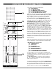
BLOCK DIAGRAM 14
SERVICE FOR YOUR NADY AUDIO PRODUCT (U.S.) Should your NADY AUDIO product require service, please contact the Nady Service Department via telephone at (510) 652-2411, or e-mail at service@nadywireless.com. (International) For service, please contact the NADY AUDIO distributor in your country through the dealer from whom you purchased this product. DO NOT ATTEMPT TO SERVICE THIS UNIT YOURSELF AS IT CAN BE DANGEROUS AND WILL ALSO VOID THE WARRANTY. NADY SYSTEMS, INC.