U-800 UHF 800-Channel Wireless System OWNER’S MANUAL
CONTENTS 1. INTRODUCTION.................................................................................2 2. USING THIS MANUAL........................................................................2 3. SYSTEM FEATURES.............................................................................3 4. QUICK USER CONTROLS GUIDE.........................................................4 5. SYSTEM OPERATION..........................................................................8 6.
. SYSTEM FEATURES U-800 RECEIVER • Unsurpassed state-of-the-art PLL UHF performance with 120dB dynamic range and longrange operation, up to 500 ft.
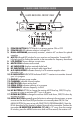
. QUICK USER CONTROLS GUIDE 3 2 U-800 RECEIVER: FRONT VIEW 4 3 16 5 18 1 9 11 10 12 6 17 13 14 7 8 15 1. POWER BUTTON BUTTON push in to power receiver ON or OFF 2. POWER LED LED indicates receiver is turned ON 3. DUAL ANTENNAS permanently mounted., rotate to 45° as shown for optimal reception 4. ASC/IR infrared LED window for sync receiver and transmitter. Transmits LED Infrared signal for linking the receiver to the transmitter for frequency downloads 5.
SCAN and IR automatically for the open channel. The IR INDICATOR will flash for 2 seconds. If the IR data download is successful, the receiver’s RF (8) and A/B INDICATORS (9) will also be on, indicating channel transfer is complete. See also section “6. Selecting Group/Channel, IR Programming and Simultaneous Multichannel Operation” U-800 RECEIVER: BACK VIEW 19 20 21 22 19. UNBALANCED LINE OUT ¼” JACK Line level audio output, adjustable with Volume control 20.
UH-800 HANDHELD TRANSMITTER: FRONT AND BOTTOM VIEW 28. MIC BALL/ ANTENNA windscreen also functions as antenna, so for best operating range do not handle this antenna during use 29. BATTERY COVER unscrew CCW to open battery tube to insert batteries 30. AUDIO INPUT LEVEL normally set at middle position, turn knob with small flat head screw driver for optimum sound 31. TWO AA BATTERIES operating from two AA batteries 32.
UB-800 BODYPACK TRANSMITTER: FRONT VIEW 38. A NTENNA Removable antenna—should be attached during operation 39. I NPUT JACK Locking 3.5mm mini-jack for connecting audio input cord from lapel mic (LT), Headmic™ (LT/HM), or instrument (GT) cable 40. A UDIO MUTE slide the switch to ON or OFF to mute audio with transmitter powered on 41. B I-COLOR BATTERY STATUS LED indicates green for strong usable battery and red for low battery needing replacement 42.
5. SYSTEM OPERATION U-800 RECEIVER Button Function The POWER ON Button (1) is used to power receiver ON or OFF. When the power button is pressed, the POWER LED (2) and the white backlight on the LCD DISPLAY (5) will light up indicating the receiver is ready. Press the Power button again to turn off the receiver. The power LED and the backlight on the LCD will be off indicating the receiver is off. At power-off the U-800 receiver will store the last settings entered and re-display them at power-on.
Powering the Receiver Plug the AC/DC ADAPTER (23) provided into the DC INPUT JACK (20) on the back of the receiver. Then plug the power supply into an AC outlet. (Note: Any 22V DC source with 400mA capability can also be used.) Press the POWER SWITCH (1) once to turn on the receiver. The POWER ON LED (2) and the LCD DISPLAY (5) will now light and the receiver is operational. Adjusting Antennas The U-800 has two permanently attached, flexible elbow ANTENNAS (3) for diversity reception.
Audio Level and Peak LED Indicator SYSTEM OPERATION The U-800 receiver has a 5 bar AF LCD (7) display that typically shows a few bars indicating normal level audio signal from the transmitter. Occasional flickering of the fifth AF LCD (peak level) on loud inputs to the transmitter is normal. If the AF LCD lights up full bars continuously decrease the input audio level to the transmitter or overload distortion may result.
Programming the U-800 to the Selected Group/Channel (frequency) The Receiver must be programmed for a Group/Channel (frequency) first then automatic synchronization using the IR ASC™ Sync function to the transmitter. For system set up procedures, see next section “6. Selecting Group/Channel, IR Programming and Simultaneous Multichannel Operation” UH-800 HANDHELD MICROPHONE TRANSMITTER (HT) Setting up the UH-800 Transmitter The UH-800 requires two AA alkaline or NiMH batteries to operate (do not mix types).
Note: : The windscreen of the UH-800 functions as a built-in antenna. For proper operation, never remove the windscreen during use, or exchange with another type. For optimum range maintain line-of-sight between the transmitter and the receiver whenever possible. Holding the microphone tightly, bridging across the windscreen and Mic tube, will also lessen range. Hold by the Mic tube housing only for optimum operation. Note: Observe care in selecting P.A.
To preserve battery life, turn the transmitter off when not in use. To turn the transmitter off, slide the POWER ON/OFF (42) switch to the OFF position. The BATTERY STATUS LED (41) is not lit up, indicating the unit is off. The MUTE ICON (6) on receiver should be on, muting the audio out. At power off the transmitter will store the last settings entered and re-display them at the next power on. The default factory setting is Group 11, Channel 01.
Connecting Input Audio Source Lapel/Head Mic Uses (UB-800 LT/HM) The mini 3.5mm locking INPUT JACK (39) is for connecting the audio input from a lavaliere/lapel Mic (LT), a Head Mic™ (HM), or an instrument (GT) cable, depending on which transmitter version is being used. Secure the connection to the cable by tightening the cable mini plug’s outer ring counterclockwise. When ready to play, slide the AUDIO MUTE ON/OFF SWITCH (40) to the ON position to un-mute the audio.
after receiver is powered off. This facilitates easy setup by enabling quick selection of stored channels for any group, i.e, selecting any group will automatically display the last channel selected for that group. See section “11. U-800 Frequency Lists” for available channels in each group. The previous group and channel used is stored in memory automatically when receiver and transmitter are turned off after operation.
Receiver/Transmitter ASC™ IR Sync Manual Programming To manually program the pre-selected Group/Channel (frequency) from the receiver to the transmitter, place the transmitter’s IR RECEPTOR SENSOR WINDOW (37, 44) 6-12” away from the receiver’s IR WINDOW (4). Press the MENU BUTTON (18) four times to the IR Screen Display and then press the UP BUTTON (16) to start IR programming. The flashing IR INDICATOR (10) icon indicates IR transmission is in progress.
7. CAUTIONS AND TROUBLESHOOTING Feedback Avoid acoustic feedback (howling or screeching) by taking care in selecting PA volume, transmitter location and speaker placement. Please also note the pickup pattern characteristics of the microphone selected. Unidirectional microphones are more resistant to feedback. However, they pick up sound sources best that are directly in front of the microphone.
8. MISCELLANEOUS TIPS • The receiver antennas should be kept away from any metal surfaces whenever possible as they can reflect away or shield the incoming RF signal. • If the receiver’s volume control is set too high, it may overdrive the input of the attached audio mixer, causing distortion. Conversely, if the output is set too low, the overall signal-to-noise ratio of the system may be reduced, causing noticeable hiss.
9. SPECIFICATIONS U-800 OVERALL SYSTEM PERFORMANCE Operating Frequency Range 470MHz–510MHz, two Bands Freq. Synthesized (800 channels switchable) 25kHz/step PLL system frequency stability <0.005% Frequency Response 50Hz-18kHz +/-3dB Dynamic Range 120dB Harmonic Distortion <0.
UB-800 BODYPACK TRANSMITTER RF Output Power +17dBm Max, +14dBm (25mW typical) Harmonic/Spurious Emission -50dBc normal Input Impedance 4.7k Ω (Lavalier); 500 k Ω (Instrument) Controls Power and Audio ON/OFF switches, Input Level Input Connector Locking 3.5mm mini-jack LED Display Bi-Color - Power ON (GREEN) and Low Battery ON (RED) Antenna Type External Removable Battery Type 2 x AAA alkaline or NiMH Battery Life 6-8 Hours typical, alkaline Dimensions 3.25”W x 2.18”D x 1”H (8.25cm x 5.53cm x 2.
11. U-800 FREQUENCY LISTS Band 1: U-800 Frequency Listing Groups from 11 to 1A (470.000MHz-489.975MHz) FACTO RY PRESET CHANNELS CH CH CH CH 1 2 3 4 CH 5 CH 6 CH 7 CH 8 CH 9 CH 10 CH 11 CH 12 CH 13 CH 14 USER SELECTABLE CHANNELS G roup 11 470.325 470.725 471.225 472.025 G roup 12 470.025 470.625 471.425 472.425 G roup 13 470.050 470.925 472.125 473.625 473.025 474.425 475.125 476.325 476.625 479.125 482.125 484.125 488.325 489.425 474.025 476.025 478.825 483.025 486.025 489.225 476.025 479.025 483.
12. OPTIONAL ACCESSORIES ERM-12 Single rack mount kit for one U-800 receiver ERM-22 Dual rackmount kit for two U-800 receivers, includes EJC-3 joining clip 13. SERVICE INFORMATION In the U.S. If you are experiencing operational problems with your system, please refer to the Support page at www.nady.com for assistance. Should your wireless system require service, please contact the Nady Service Department at (510) 652-2411 for a Return Authorization (R/A) Number and service quote (if out of warranty).
14. ONE YEAR LIMITED WARRANTY Nady Systems, Inc. warrants to the original consumer purchaser that the unit is free from any defects in material or workmanship for a period of one year from the date of original retail purchase. If any such defect is discovered within the warranty period, Nady Systems, Inc. will repair or replace the unit free of charge, subject to verification of the defect or malfunction upon return to Nady Systems.
Consumer Alert Most users do not need a license to operate this wireless microphone system. Nevertheless, operating this microphone system without a license is subject to certain restrictions: the system may not cause harmful interference; it must operate at a low power level (not in excess of 50mW); and it has noprotection from interference received from any other device.