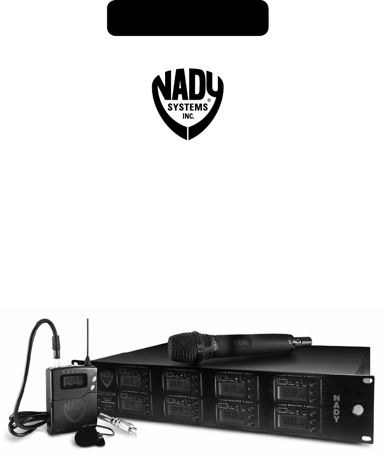
Owner’s Manual 8W-1KU 1000-Channel UHF Dual Receiver Wireless System
Contents Introduction.............................................................................................................................. 2 Using this Manual..................................................................................................................... 2 System Features...................................................................................................................... 3 Quick User Controls Guide................................................................
System Features 8W-1KU System • Unsurpassed state-of-the-art PLL UHF performance with 120dB dynamic range and operation up to 500 ft. line-of-sight • 1000 user-selectable UHF frequencies per band 8W-1KU Octo Receiver • Unsurpassed state-of-the-art PLL UHF performance with 120dB dynamic range and operation up to 500 ft.
Quick User Controls Guide 8W-1KU Receiver: Front View
1. POWER BUTTON Press for two seconds to turn receivers ON-OFF 2. DIVERSITY A/B INDICATOR Indicates receiver A or B is active when transmitter is on 3. AF PEAK LED Shows flickering GREEN LED is normal or solid GREEN LED is for maximum audio allowable 4. IR Infrared LED transmitter window for linking the RX to the TX for download frequency 5. AUTO-SCAN/ASC (IR SYNC) BUTTON Long press (hold ~2 seconds) for AUTO-SCAN to locate a clear channel to use.
Quick User Controls Guide 8W-1KU Receiver: Rear View
13. RACK EARS Left and Right rack ears are built into the unit 13a. FAM-K2 ANTENNA EXTENSION CABLES (Optional) Attach coax cables with BNC connectors from back antenna jack to rack ear holes for front antenna mounting configuration 14. RF CONNECTORS Antenna jack A for RF True Diversity reception 15. BALANCED MIC OUT Audio output connection for each receiver—fixed Mic level 16.
Quick User Controls Guide HT-1KU Handheld Transmitter
22. BATTERY COVER Unscrew CW and pull down to insert two AA alkaline batteries 23. MIC BALL Windscreen/dust cover 24. LCD DISPLAY For indication of GRP (00-09)/ CH (00-99), AUDIO INPUT LEVEL (0dB to -30dB), and BATTERY status (5 bars and “BATT.”) See 30/31/32/33 in HT-1KU transmitter diagram above for detail LCD display indicators. 25.
Quick User Controls Guide BT-1KU Bodypack Transmitter (LT, LT/HM or GT)
37. INPUT JACK 3.5mm locking mini jack for connecting audio input cord from lapel mic (LT), Headmic™ (LT/HM), or instrument (GT) 38. POWER OFF/MUTE/ON SWITCH Slide power switch to ON or OFF to turn ON-OFF, set to MUTE to turn power on with audio muted 39. ANTENNA Permanently attached antenna 40. LCD DISPLAY For indication of GRP (00-09)/CH (00-99), AUDIO INPUT LEVEL (0dB to -30dB), and BATTERY status (5 bars and “BATT.
System Operation 8W-1KU Receiver Installing Antennas Install antennas on back by connecting the two Antennas (21) included with your system onto the two RF Connectors (14/19) located on the back of the 8W-1KU receivers. The two antennas must be installed in order for the diversity circuit to work properly. The optimal positions of the antennas are 45° from the receiver and 90° from each other.
During manual programming, the selected function will flash for five seconds or press the Set button to confirm the selection and the display will return to the main menu. The AUTO-SCAN / ASC (IR Sync) Button (2) has two functions: • Long press (hold ~2 seconds) for AUTOSCAN for finding a clear channel within the frequency band (with all TXs turned off at this time). Clockwise running segments on the LCD display show the scanning is in progress which normally takes ten seconds.
will flash for five seconds or press the Set button to confirm the selection and the display will return to the main menu. For detail how to IR Sync the TX, see IR Sync Programming in Programming sections of HT-1KU and BT-1KU transmitter sections.
Your 8W-1KU receiver is now operational and ready to use. Once you have completed the above steps, proceed to the following instructions for the HT-1KU Handheld or BT1KU Instrument transmitter. Note: Only one transmitter can be used with one receiver. It is not possible to use two transmitters on the same frequency and mix the output of these transmitters into one wireless receiver.
HT‑1KU Handheld Microphone Transmitter Setting up the Transmitter The HT-1KU requires two AA size batteries to operate. To install the batteries onto the battery compartment, unscrew the Battery Compartment Cover (22) by turning counterclockwise until loose and slide down the cover, exposing the Battery Compartment (35). Insert two fresh AA batteries (36) according to the correct polarity as indicated on the transmitter body.
IR Sync Programming: Use the wireless IR LED Receptor Sensor (34) to download pre-programmed channels from the receiver. Start programming by holding the IR Receptor Sensor/Window about 6” in front the receiver to be used. On the receiver, when short pressing the ASC IR Sync Button (5), while the main menu is displayed, the IR Infrared LED (4) will light up red and stay for about five seconds. This indicates IR transmission is in progress and IR data is transferring during this period.
decrease the RF power (reduced range). This is a useful feature as the “L” setting increases battery life and also optimizes the number of channels that can be used simultaneously in a given location. Use this setting for normal use not requiring maximum operating range. A range walk test before use will determine which setting is best for your application. Slide the On/Off switch to the “ON” position and the microphone is now ready to use.
should stay lit as possible, indicating usable battery strength. As the batteries weaken, fewer of the level indicators stay lit until only one bar shows, which will then flash to warn that the batteries are now too low and should be replaced as soon as possible. To preserve battery life, turn the transmitter off when not in use. To turn the transmitter off, slide the Off/Mute/On switch to “MUTE” and then “OFF”. The LCD will display “OFF”, no LCD or backlight is lit up and the unit will be off.
at -10dB for LT/HM and 0dB for GT. These settings are optimal for most applications. For normal operation, the transmitter should have the same Group/Channel as displayed on the receiver. The default factory setting is Group 01 (Receiver 1) and 02 (Receiver 2), 03 (Receiver 3) and 04 (Receiver 4), Group 05 (Receiver 5) and 06 (Receiver 6), 07 (Receiver 7) and 08 (Receiver 8) for all receivers. After programming is finished, close the battery compartment door, ensuring that it latches.
Specifications SYSTEM OVERALL SPECIFICATIONS Operating Frequency Range Freq. Synthesized PLL System Frequency Stability Frequency Response Dynamic Range Harmonic Distortion Modulation Operating Range (U.S.) Band 1: 672.000-696.975MHz, (Int.) Band 2: 795.000819.975MHz (1000 channels switchable) 25kHz/ step <0.005% 30Hz-18kHz +/-3dB 120dB <0.
LCD Display Group/ Channels/ Input Volume/ Battery Levels Antenna Type External fixed Battery Type 2 x AA alkaline batteries operation Battery Life 8-10 Hours typical Dimensions 2.5”W x 3.25”H x 1-13/16”D (6.35cm x 8.3cm x 1.82cm) Weight (w/o batteries) 3.8 oz (0.108 kg) Housing Construction Metal (25mW typical), LOW: +4dBm (2.
Cautions and Troubleshooting Feedback Avoid acoustic feedback (howling or screeching) by taking care in selecting PA volume, transmitter location and speaker placement. Please also note the pickup pattern characteristics of the microphone selected. Unidirectional mics are more resistant to feedback. However, they pick up sound sources best that are directly in front of the mic.
Miscellaneous Tips • For optimal operation with external antennas, low loss RF shielded cable should be used and the length of the cable should not exceed 10 ft. (3 m). • Position the receiver so that it has the least possible obstructions between it and the transmitter. Line-of-sight is best! • The receiver antennas should be kept away from any metal surfaces whenever possible as they can reflect away or shield the incoming RF signal.
• When using the BT-1KU bodypack for instrument use: Scratchy noises can sometimes occur when an electric guitar with dirty pots or connections is used with a wireless system. Therefore, the supplied capacitor provides first-order filtering of the RF signal from the cord into the guitar and eliminates virtually all scratchy noises.
Frequency Frequency Plan Band 1 (U.S.): 672.000-696.975MHz Band 2 (International): 795.000-819.975MHz 25KHz per step (1000 Channels) U.S. The 8U-1KU System Includes: User’ Manual (This manual) Two antennas Lav Mic for LT AC/DC power adaptor Main Receiver Unit 8 combination (HT/ LT/GT) transmitters GT cable for GT Accessories Part Number Description IC-U1K Instrument cable for BT-1KU/GT transmitter, 3.
One Year Limited Warranty Nady Systems, Inc. warrants to the original consumer purchaser that the unit is free from any defects in material or workmanship for a period of one year from the date of original retail purchase. If any such defect is discovered within the warranty period, Nady Systems, Inc. will repair or replace the unit free of charge, subject to verification of the defect or malfunction upon return to Nady Systems.
6701 Shellmound Street | Emeryville, CA USA 94608 T 510.652.2411 | F 510.652.5075 | www.nady.