
- Nady PEQ-5B 5-BAND PARAMETRIC EQUALIZER OWNER'S MANUAL

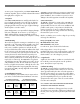

CONTROLS AND CONNECTIONS
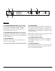
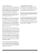
FRONT PANEL
The Nady PEQ-5B has five parametric filters organized in five
different frequency bands. A 12-segment LED display shows
the input or output level, and there is both a master low-cut
and high-cut filter.
1. POWER SWITCH
To turn the unit ON or OFF, press the upper or lower portion
of this button.
2. MASTER INPUT/OUTPUT LEVEL METER DISPLAY
This 12-segment LED meter is used to monitor the signal lev-
els, so as to avoid overload distortion. The display shows the
input or output level as selected by the AUDIO IN/OUT switch
(INPUT is selected with the switch pressed in). The top red LED
lights at a level of about +18 dB, which is about 3 dB below
clipping.
(Note: Extreme boost settings in combination with a high input
level can cause overload clipping. If this happens, reduce the
input level as necessary with the INPUT control.)
3. MASTER AUDIO IN/OUT SWITCH WITH LED INDICATOR
This is used to enable/disable the entire equalizer section in
the audio path, allowing A/B comparisons between the
processed and unprocessed signals. The switch uses a relay-
controlled hard-bypass function, so that if it is not pressed in
or if the unit is switched off, the inputs are directly connected
to the outputs. The switch also selects the input or output sig-
nal for display on the INPUT/OUTPUT LEVEL meter. The LED
lights when the switch is IN.
6
6
3
4
5
4. MASTER INPUT CONTROL
Use this CONTROL TO DETERMINE THE INPUT LEVEL TO THE
UNIT. It can be set from -15 to + 15dB.
5. MASTER LOW CUT CONTROL
Use this control to adjust the lower cutoff frequency of the
PEQ-5B. The high pass filter can be tuned from 10 to 400 Hz.
In the 10 Hz position the signal passes unchanged.
6. MASTER HIGH CUT CONTROL
Use this control to adjust the upper cutoff frequency of the
unit. The low-pass filter can be tuned from 2.5 to 30 KHz. In
the 30 KHz position the signal passes unchanged.
7. BAND LEVEL CONTROLS
Use this control to determine the amount of level boost/cut for
each band. The setting ranges from -15 to + 15 dB.
8. BAND IN/OUT SWITCHES WITH LED INDICATORS
Use these switches to enable/disable specific bands in the
audio path. The LED lights when the switch is IN.
9. BANDWIDTH CONTROLS
Use these controls to determine the "Q" or slope of the filter in
each band. Settings range from 0.03 (Q=43) to 2 octaves
(Q=0.67).
10. BAND FREQUENCY CONTROLS
Use these controls to select the filter's center frequency in each
band. This can be any frequency within that band's frequency
range.
INPUT/OUTPUT LEVEL(dB)
-30 -24 -18 -12 -6 -3 0 +3 +6 +9 +12 +18
PEQ-5B
5 Band
Parametric
Equalizer
20kHZ-400kHz
BAND
1
60HZ-1kHz
BAND
2
150HZ-2.5kHz
BAND
3
500HZ-8kHz
BAND
4
1kHZ-20kHz
BAND
5
POWER
AUDIO HIGH CUTLOW CUT
INPUT
IN
dB
-10
-10
0
+5
-15
+15
75
110
10 400
22
25
50
Hz
7
10
15
2.5 30
KHz
OUT
-5
+10
200
3.5
22
LEVEL
BANDWIDTHAUDIO
FREQUENCY
IN
-5
dB
-10
-10
0
+5
-15
+15
0.8
1.2
0.03 2
22
0.1
0.4
OCTAVE
80
110
150
20 400
Hz
OUT
-5
+10
40
1.6
250
-10
LEVEL
BANDWIDTHAUDIO
FREQUENCY
IN
-5
dB
-10
0
+5
-15
+15
0.8
1.2
0.03 2
0.1
0.4
OCTAVE
160
250
350
60 1k
Hz
OUT
-5
+10
80
1.6
550
-10
IN
-5
dB
-10
0
+5
-15
+15
0.8
1.2
0.03 2
22
0.1
0.4
OCTAVE
400
600
900
150
2.5k
Hz
OUT
-5
+10
200
1.6
22
-10
LEVEL
BANDWIDTHAUDIO
FREQUENCY
IN
-5
dB
-10
0
+5
-15
+15
0.8
110
0.03 2
22
0.1
0.4
OCTAVE
1.5
1.8
2.7
2.5 30
kHz
OUT
-5
+10
0.7
1.6
4.6
-10
LEVEL
BANDWIDTHAUDIO
FREQUENCY
IN
dB
-10
0
+5
-15
+15
0.8
1.2
0.03 2
22
0.1
0.4
OCTAVE
7
4
6.5
2.5 20
KHz
OUT
-5
+10
1.5
1.6
10
LEVEL
BANDWIDTHAUDIO
FREQUENCY
1.4k
1
10
8
7
9
2